My new book on modeling historical aircraft is already available in the web shops. This is the second volume of the new (fourth) edition of the “Virtual Airplane” guide:

Continue reading New Guide about Modeling Historical Aircraft
My new book on modeling historical aircraft is already available in the web shops. This is the second volume of the new (fourth) edition of the “Virtual Airplane” guide:
Continue reading New Guide about Modeling Historical Aircraft
This post is dedicated to a minor feature, which I have found surprisingly demanding: modeling the grooves pressed in the curved surfaces of the aircraft panels. In the SBD you can see some of such reinforcements on the inner cowling, behind the cylinder row (Figure 95‑1):
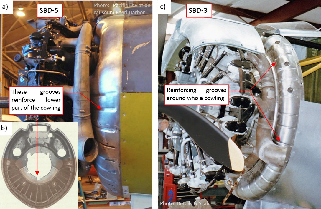
They are 0.7-1.0” wide (Figure 95‑1a) and span over the inner cowling along its radial directions (Figure 95‑1b, c). In the SBD-5 and -6 these reinforcing grooves occur only on the lower part of the cowling (Figure 95‑1b), while in the earlier versions (SBD-1, -2, -3, and -4) they are also present on the upper part (Figure 95‑1c).
Even when the flaps on the NACA cowling are closed, you can still see rounded endings of these grooves around the cowling rear edge (Figure 95‑2):
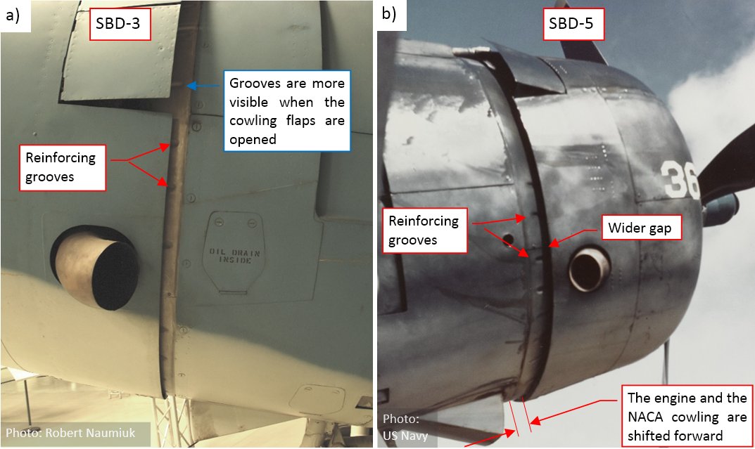
In the earlier versions (SBD-1..SBD-4) they appear on the narrow strip behind the NACA cowling (Figure 95‑2a). You can see more of the upper grooves when the NACA cowling flaps are set wide open. In the SBD-5 and -6 the engine and the NACA cowling were shifted forward by 3.5”, and the gap between the NACA ring and the inner cowling is wider. Thus, in these versions you can see even longer fragments of the grooves behind the NACA cowling (Figure 95‑2b).
Such grooves appear on many sheet metal elements, so I decided to write this post as a small tutorial that teaches how to recreate these elements. Thus, do not be surprised when I list the detailed Blender commands in the text below.
Continue reading Recreating Grooves in the Sheet Metal Panels
After “mounting” the R-1820 engines into my SBD models, I decided to recreate some details of the inner cowling (the cowling panels placed behind the cylinder row). In this post I will form the missing parts of the carburetor air ducts, hidden under the NACA ring. There are significant differences in this area between various SBD versions, which never appeared in any scale plans, or in any popular monograph of this aircraft. I think that the pictures presented below highlight these differences. They can be useful for all those scale modelers who are going to build the SBD “Dauntless” models with the engine cowlings opened. (Sometimes you can encounter such advanced pieces of work on the various scale model contests).
Let’s start with the SBD-5s (and -6s), which are better documented (because they were produced in much larger quantities). They had a dual intake system, of the filtered/non-filtered air, which I discussed it in the previous post. I already recreated the two intakes of the filtered air, placed between the engine cylinders. Now I have to create the central, direct air duct and its opening at the top of the internal cowling.
Figure 94‑1 shows the initial state of my SBD-5 model:

Continue reading Differences between Dauntless Versions: Carburetor Air Duct
In my previous post I have finished the second variant of the R-1820-52 “Cyclone” engine, which was used in the SBD-3 and -4. (It looks like the earlier R-1820-32 model, mounted in the SBD-1 and -2). In the resulting Blender file linked at the end of that post you will find two “Cyclone” versions: the R-1820-52 (for the earlier SBD versions, up to SBD-4) and the R-1820-60 (for the SBD-5 and -6). Each of these engines has its own “scene”.
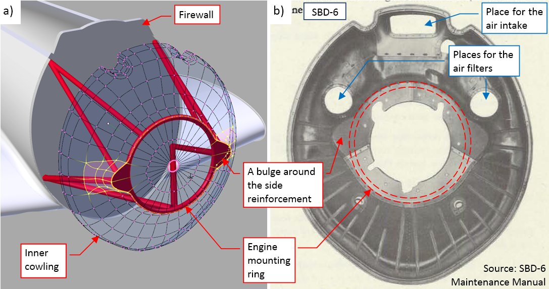
To “mount” these engines into my SBD models, I imported both scenes to the main Blender file. I defined each engine variant as a group, to facilitate placing them in the aircraft models as the group instances. I also added the firewall bulkhead and updated the shape of the cowling behind the cylinder row. (I will refer to this piece as the “inner cowling”). So far I did not especially care for the shape of its central part, hidden below the NACA ring. Now I updated it for the real size and shape of the engine mounting ring (Figure 93‑1a):
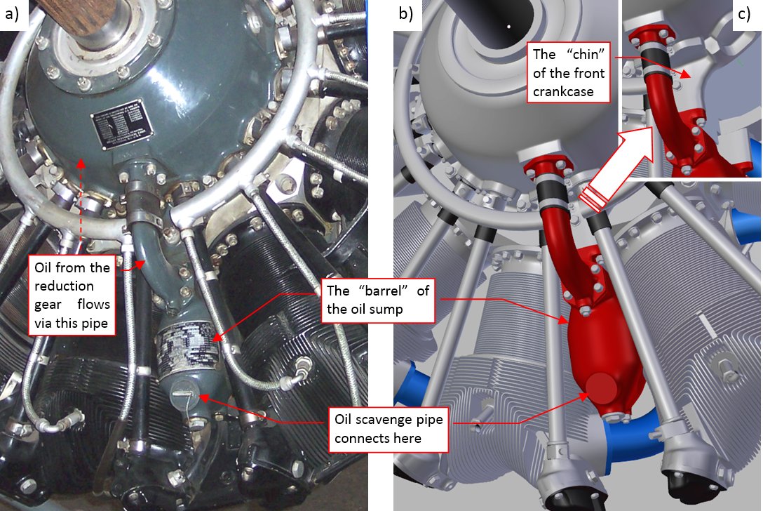
In this post I will finish my model of the R-1820-52 “Cyclone”. (This is the continuation of the subproject that I started reporting in the previous post). Figure 92‑1 shows the oil sump, used in this engine:
Continue reading Recreating the Wright R-1820-52 “Cyclone” (2)
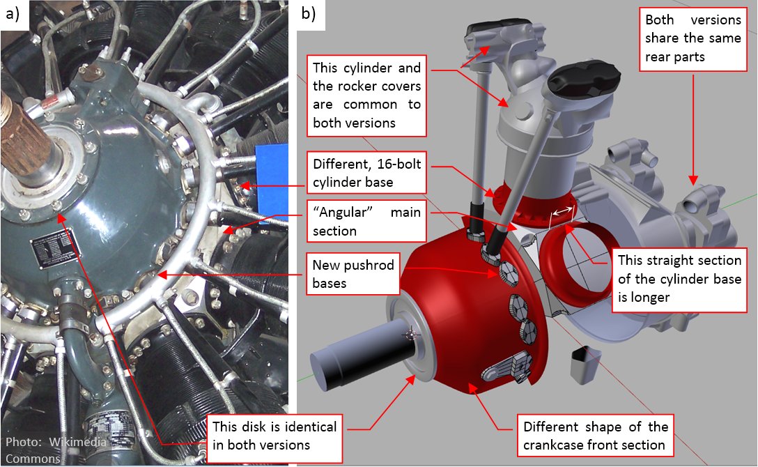
Following the conclusion from my previous post, I have to recreate yet another “Cyclone” version: the R-1820-52, used in the SBD-3 and SBD-4. Fortunately, the R-1820-32, used in the SBD-1 and SBD-2, seems to be identical (at least – as viewed from the front), thus I do not need to recreate this “Cyclone” variant. I will describe the modeling process of the R-1820-52 in the “fast forward” mode, compressing the whole thing to two posts: this and the next one.
Initially I identified just two differences: the shape of the front crankcase section and the different ignition harness. I assumed that I will be able to reuse most of the R-1820-60 components. I had discovered most of the issues described in my previous post while working on this R-1820-52 version. In fact, it occurs that such an attempt to create a 3D model of such an engine is like an scientific experiment: it verifies the initial hypothesis and reveals the new facts that otherwise would be overlooked.
I started by renaming in the source Blender file the scene that contains the previously finished engine as “R-1820-60” (the “military” symbol of an engine belonging to the “Cyclone” G200 family). Then I created a new scene, named “R-1820-52” (the G100 family). This is my new “working place”. I copied there (precisely speaking: “linked”) some of the “R-1820-60” parts that were common for the G100 and G200 family. In this “*-52” version I followed the same “building path” which I used for the previous one. So I began with the crankcase and the basic cylinder elements (Figure 91‑1):
Continue reading Recreating the Wright R-1820-52 “Cyclone” (1)
In this post I will finish all the remaining details on the front of the R-1820 engine. (As I mentioned in earlier posts, this model is intended for the outdoor scenes, with closed cowlings. That’s why I recreated the more complex rear part in a simplified form, just to check if it fits properly to the airframe).
One of the most exposed “Cyclone” details is the variable-pitch propeller governor (Figure 89‑1):
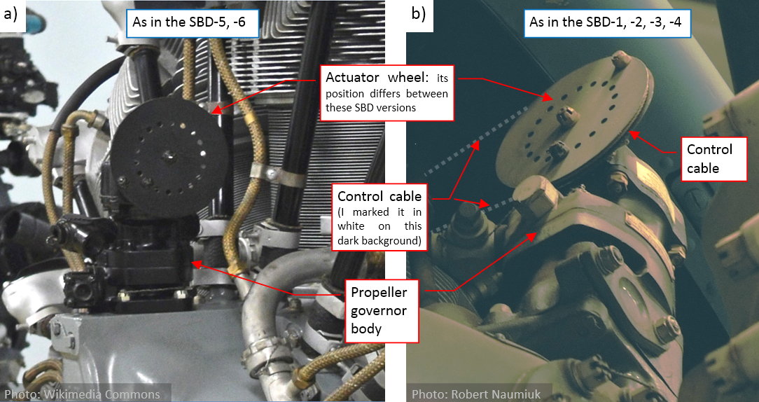
This is an additional unit that controls the pitch of the Hamilton-Standard propeller. (It controls the oil pressure, which determines the actual pitch of the propeller blades). You can find it in every aircraft, but it is often dismounted from the “standalone” engines, presented in the museums. The large wheel at its top is used as an actuator attachment. The actuator can be a pushrod or a cable from the cockpit. In the case of the SBD (and many other WWII aircraft) it was a control cable (Figure 89‑1b). The engine depicted in Figure 89‑1a) is a standalone museum exposition, thus it lacks such a cable.
In my previous posts (published in May and June) I focused on the cylinder. I think that it is the most difficult part of every air-cooled engine. Since that time I have made a significant progress, which I will report during nearest three weeks.
Let’s start with the rear section of the crankcase (behind the cylinders). Do you know how difficult is to find a decent photo of this area? The original pictures from the “Cyclone” manual are of moderate quality (Figure 88‑1a):
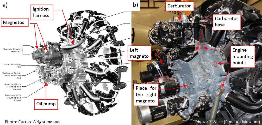
The modern photo (Figure 88‑1b) reveals more details. In general, it looks that the rear part of the crankcase is formed from two cylindrical segments. The intake pipes extend from the first (i.e. forward) of these segments. (There is a centrifugal supercharger inside). The upper part of the last segment contains rectangular air scoop, which also provides the mounting points for the carburetor (Figure 88‑1b). The rear wall of this segment forms the base for various auxiliary aggregates: magnetos, oil pump, starter, etc. As you can see in Figure 88‑1b), aggregates from the R-1820 exposed in the Pima Air Museum differ from the manual photo (Figure 88‑1a). I think that such equipment could be used in the B-17s. On this photo I also finally determined an important feature of the R-1820 geometry: its mounting points. (They are dimensioned on the installation drawings, but I had to find them among all these nuts and bolts that you can see on the crankcase).
In this post I will finish the first cylinder of the R-1820 “Cyclone”. It will be the “template” object, which I will clone eight times around the crankcase when I finish the other parts of this engine.
Although in my previous post the cylinder head received the full set of its cooling fins, it still lacks some details. One of them are the reinforcements of the valve covers:
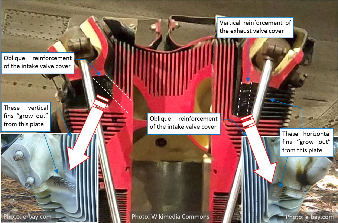
As you can see, these reinforcements break the symmetry of the left and right valve covers. Both of them resemble a thick plate, but one is oblique, while the other is vertical. They are not the most prominent features of this cylinder head, and it took me some hours to determine their probable shape. Finally I classified them as the secondary features of the covers, which I have to recreate, for the assumed level of details.
The fins of the air-cooled cylinder heads are a state-of-art piece of metallurgy (Figure 86‑1):
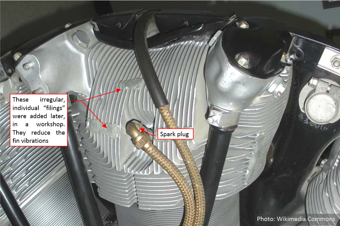
At the first glance, it is hard to believe that they were cast as a single piece. But when you look closer, you will discover that these fins “grow up” from the solid parts of the head as naturally, as the hair from the head (Figure 86‑2):
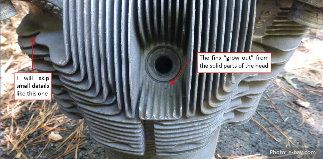
Try to imagine the shape of molds used in the production of these parts, and the challenges faced by their manufactures! (There is an interesting post about this. It describes production of the R-1830 Twin Wasp cylinders). Basically, modern producers of the heads for the air-cooled aircraft engines use the same technology as eighty years ago.
In my model I will recreate these fins in a somewhat simplified form, as a few separate Blender objects. I will also skip some fine details of their shape (for example the small features that I marked in the figure above). Such a simplification conforms the moderate level of details that I assumed for this model. It is always possible to make a more detailed version of this object later.
