In this post I will finish the first cylinder of the R-1820 “Cyclone”. It will be the “template” object, which I will clone eight times around the crankcase when I finish the other parts of this engine.
Although in my previous post the cylinder head received the full set of its cooling fins, it still lacks some details. One of them are the reinforcements of the valve covers:

As you can see, these reinforcements break the symmetry of the left and right valve covers. Both of them resemble a thick plate, but one is oblique, while the other is vertical. They are not the most prominent features of this cylinder head, and it took me some hours to determine their probable shape. Finally I classified them as the secondary features of the covers, which I have to recreate, for the assumed level of details.
First I formed the oblique reinforcement of the intake valve cover. I extruded it from the existing mesh (Figure 87‑2):

When you compare this mesh (in Figure 87‑2a) with the last picture in my last-previous post (Figure 85‑11), you will clearly see that I had to remake this shape again. (I was wrong, then). At this moment I declined to create the last “block” that closes the array of the vertical fins at this cover (Figure 87‑2b), because it would be too difficult to merge such a feature within the current mesh. I will come back to this issue later in this post.
In the case of the vertical reinforcement of the exhaust valve, I encountered similar problem: it would be quite difficult to extrude such a shape from the existing mesh. However, this time I decided to make it as a separate object (Figure 87‑3):

The next element that I recreated is the top cover of the rocker (Figure 87‑4b):

After some initial trails, I decided that the previous, simplified version of this element that I made some weeks ago is useless. (You can still see it in Figure 87‑5b). Thus I started a new top cover from the scratch. I formed it using the same reference drawings that I used for the main rocker covers (Figure 87‑4a). The fillets of this shape (I marked them in yellow) are created using a multi-segment Bevel modifier. However I had some troubles with the radius of the upper fillet (Figure 87‑4c). It occurred that the Bevel modifier can alter the fillet radius along the rounded edge. What’s worse, I could not obtain the larger radius at the higher corner of this cover, because their proportions and sizes were restricted by the height of the cover shorter side (Figure 87‑4c). Well, the difference was not so big, thus I accepted it.
In the next step I prepared four conical shapes in the places where this cover had recesses around the bolts (Figure 87‑5a):
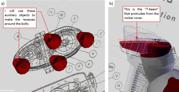
In the “old” object, still located on the top of the rocker cover, I also created a perpendicular “T-beam” (Figure 87‑5b). I formed it there, because I needed to use the outer, circular contour of this engine as the reference. It was just prepared for later.
Then I started to create the recesses around the bolts. After applying each of the Boolean modifiers I had to “clean” this mesh by removing the extra vertices and edges (Figure 87‑6a):

Then I spent significant amount of time on improving the shape of the fillets around these recesses (initially they were in a really bad shape). Basically, I had to disperse the fan-like edges from the forward recess along the mesh, and add some new “middle” edges (Figure 87‑6b). Finally, I placed this rocker top cover on the cylinder head and joined it with the “T-beam” object that I had prepared some steps before. Note that I left these two meshes disconnected – it looks quite good as it is (especially in black – see Figure 87‑7). Joining faces of this “T-beam” and the rest of this cover would require significant amount of work.
These top rocker covers are examples of the parts that do not seem difficult at the beginning. Then, after many hours spent on their vertices and edges you are discovering their “true nature”. In this case I lost most of the time on fixing the various issues along the rounded edges of the bolt recesses. If I had to make this cover again, I would sculpt these fillets manually, then eventually smoothed them using a Subdivision Surface modifier.
Comparing to these top covers, the details of the cylinder barrel were easy. In the real R-1820 its fins were made separately, from steel rings. I created them from a quarter of such a ring (Figure 87‑7):

I just used a Mirror modifier (along X and Y axis) to convert this mesh into a full ring, then multiplied it down along the barrel using an Array modifier. Finally I added the Solidify modifier, which gave these plates some thickness.
I also used a large-radius multi-segment Bevel modifier to profile the cylinder base (Figure 87‑7).
Finally I added the first bolts to this engine. Each of these objects is a clone of the same mesh. Initially I prepared two such meshes: the classic nut for the rocker top covers, and the massive head for the bolts around the cylinder base (Figure 87‑8a):
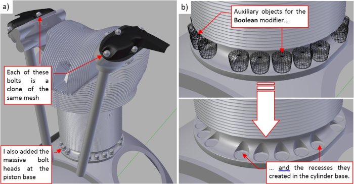
I also recreated recesses in the cylinder base around these bolts. I made it using an auxiliary object and a Boolean (difference) modifier (Figure 87‑8b). (In fact, to make the edges of these recesses more regular, I had to alter a little some faces of these auxiliary objects).
The last element of the cylinder was its upper deflector. Basically, this is just a piece of the sheet metal, “wrapped” around the cylinder head (Figure 87‑9):

Although most of this deflector surface lies in the “invisible” back area of this engine, I decided to recreate it as a whole – just for the eventual future use. (In fact, the most difficult part was to determine the approximate shape of this part). It was made from a single smoothed (by the Subdivision modifier) mesh surface. The vertical reinforcements on its sides are created as separate objects, also made from a single surface. Additional Solidify modifier gives them a non-zero thickness. Because this is the “invisible” zone of my model, I did not recreate such minor details as the bolts and rivets, here.
In general, this deflector was the last part of the cylinder. However, you never know when you find something new and will have to modify your model.
I finished this cylinder about two months ago, and then worked on the other parts of this engine. (Yes, my reports are always a few weeks late). After a month I finally decided to recreate the closing block of the fin array at the intake cover (marked in red in Figure 87‑10a). This time I made it as a separate object, to avoid tedious work of rounding all of the eventual intersection edges. I also looked for more reference pictures. One day in May I found additional detailed photos of the R-1820 cylinder head in a certain e-bay auction. When I compared them to my model, I discovered that my cylinder is missing one fin at the intake cover (Figure 87‑10):

(There were three such fins in the photo, while my model had only two). The new photos quickly revealed my error: I have to shift the forward faces of nearly all existing vertical fins to the right! (To the next fin).
In this and next paragraphs I use the “left” and “right” directions as you can see them in Figure 87‑10. The intake valve is on the left, while the exhaust valve is on the right side.
Such a movement of the 26 fins will create space for additional “shorter” fin on the left and discard one fin on the right. It also will shift the central segment of these fins that contains the hollow for the forward spark plug.
Fortunately, the structure of my model allows me to do such a modification in a relative easy way. (That’s why I hold myself in duplicating this cylinder to the latest stage of this project, and using in every of its objects as many modifiers as possible). I have introduced all these updates to the latest version of this R-1820 model, thus you will not find them in the example file that accompanies this post. (They will appear in the file that accompanies one of the future posts).
How I did it? First, I modified the shape of the “fin boundary” object, which I use to the Boolean modifier to “cut” the fins (Figure 87‑11a):

Then I shifted the “raw” faces of the fin mesh to the right by one “fin module” (0.215”). When I did it, I started switching these shifted faces to the adjacent fins (Figure 87‑11b). Finally I dropped the rightmost fin and added one fin segment on the left.
Figure 87‑12a) shows my results, while Figure 87‑12b) is the picture of an authentic R-1820 head:

The most obvious difference is the certain “angularity” of my model: it lacks many of the soft fillets and intermediate surfaces that you can see in the original head. This is the price for the relative simplicity and moderate polygon count. (The final model of this engine will have about 500 thousand faces). Making a more detailed version of this head would require much more time, and (at least) four times more faces in the final model.
However, I can also see various minor differences in the area around the exhaust (I marked it in Figure 87‑12 using a dashed line). It seems that I should shift the exhaust base to the rear, because you can see it on the photo, while it is hidden under the fins in my model. This is strange because I read the precise location of the exhaust opening from the explicit dimensions on the original installation drawings. I have also found another minor difference between this photo and the original Curtiss-Wright drawing. Thinking about it, I realized that I am using reference drawings from 1942, while the head in this photo comes from a B-17G (according the e-bay auction). This means, that it was produced no earlier than in 1944. It may happen that I found minor differences between various R-1820 production series. All in all, they appear on the rear part of the engine, which will be invisible in my model. Thus I decided to continue without fixing these findings.
Figure 87‑13 shows the current state of the model:

You can examine my model in this source *.blend file. Just remember that this is the earlier version, saved in March (before I shifted the forward fins). In the next post I describe my work on the crankcase details. After this I will recreate the spark plugs, ignition harness and the side deflectors (between the cylinders).

Man you details are simply badass! PS i think you will be happy with Blender 2.80 it has some updates done on the Bevel modifier, there are now new options. https://youtu.be/8Nuu-mzaxC0?t=419
LikeLike