Recreating the P-40B: 3D Reference of the Fuselage (1)

At this moment I am working on second volume of my book about 3D modeling.  It describes building a 3D model of a WW2 aircraft on the example of the P-40B. Preparing for this work, I discovered that the original documentation of this early P-40 variant (also known as “long nose Warhawks”) is missing. On the other hand – you can find plenty of the “short nose Warhawk” blueprints (related to the P-40D later variants), as well as some P-36 drawings. I started by picking over 1000 original Curtiss blueprints and sketches related to the P-40, XP-40, and the P-36 from the vast resources of the AirCorps Library. Then I analyzed their contents, comparing them to the available historical photos. I described this process in this and following posts, written in 2019. Ultimately I traced side view of the P-40B. I also concluded that a 3D visualization of the available ordinals will be a better reference. In the previous posts I built such a reference for the SBD Dauntless. In this and the next post will I describe similar work on the fuselage of the early P-40 variants (P-40-cu, P-40B, P-40C).

I prepared an empty Blender file. For the convenience, I placed there my side view (from this post, see Figure 102-15). As for the SBD model, I assumed that 1 Blender unit = 1 in. For the main part of this fuselage, spanning from the firewall to the rudder, I used two P-36 diagrams. First of them (dwg 75-21-140) provides locations of the fuselage stiffeners at each bulkhead. There is also its modified variant (dwg 75-21-836) for the XP-40:
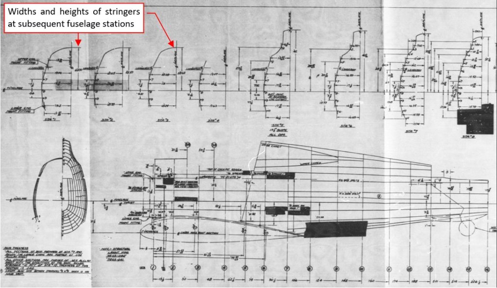
Figure 120-1 XP-40 fuselage stiffener dimensions (dwg 75-21-836)

Continue reading Recreating the P-40B: 3D Reference of the Fuselage (1)

Recreating the P-40B Engine Cowling (Side Contour)

In the previous post I finally identified Curtiss layout sketch L-10202 as description of the XP-40 geometry, as it was in February 1940. In that time Curtiss was finishing preparations for serial production of the P-40. (The first P-40 from this batch was accepted by USAAC in April 1940). This final variant of the XP-40 resembled the serial P-40-cu, except the tail wheel cover and rear glass frames, “inherited” from the P-36. However, the archival photos revealed minor differences between engine cowlings of these aircraft: the serial P-40 had longer spinner and deeper radiator cover.

It seems that all the original drawings and sketches of the early P-40s that I collected from the AirCorps Library resources describe the XP-40. Thus, first I will prepare the XP-40 side view using this original documentation. Then I will draw a P-40B side contour, using these XP-40 lines and available P-40-cu/B/C photos.

As I showed in one of previous posts, the XP-40 sketches are not only rare, but also in poor shape:

0102-01
Figure 102-1 Original sketch of the cooler air scoop (layout L-10276, in two overlapping microfilm frames)

Continue reading Recreating the P-40B Engine Cowling (Side Contour)

Verification of an Unidentified Layout Drawing

Generally speaking, the early P-40s (-cu, B, C) were “P-36 airframes with inline engines”.  Thus, the only unique first-order assembly in these P-40 variants was their engine compartment. So far it seemed that the documentation of this area was lost, and the restoration teams had to rely on archival photos and other restored P-40B/C. (A P-40B restoration teamfrom New Zealand mentioned this in their interview).

In my post from August 2019 (Fig. 98-13 and Fig. 98-14) I described a previously unnoticed layout sketch, that I found among the “uncategorized” P-36/P-40 drawings in the AirCorps “P-40” microfilm set:

0101-01
Figure 101-1 Engine cowling layout sketch (L-10202)

It can describe the geometry of the “long nose Hawk” engine cowling. In the same AirCorps Library uncategorized “pile” I also found some regular XP-40 drawings (engine mount, radiator support) and other sketches. However, the lines in all these images are faded, making them nearly unreadable. The L-10202 sketch is the most promising blueprint that I have found. In this post I will try to match this layout to the P-40B fuselage that I prepared in my previous post. I will also use photos to evaluate the results (i.e. for checking if the sketched engine cowling layout matches the real aircraft).

Continue reading Verification of an Unidentified Layout Drawing

Mounting the Engine

In my previous post I have finished the second variant of the R-1820-52 “Cyclone” engine, which was used in the SBD-3 and -4. (It looks like the earlier R-1820-32 model, mounted in the SBD-1 and -2). In the resulting Blender file linked at the end of that post you will find two “Cyclone” versions: the R-1820-52 (for the earlier SBD versions, up to SBD-4) and the R-1820-60 (for the SBD-5 and -6). Each of these engines has its own “scene”.

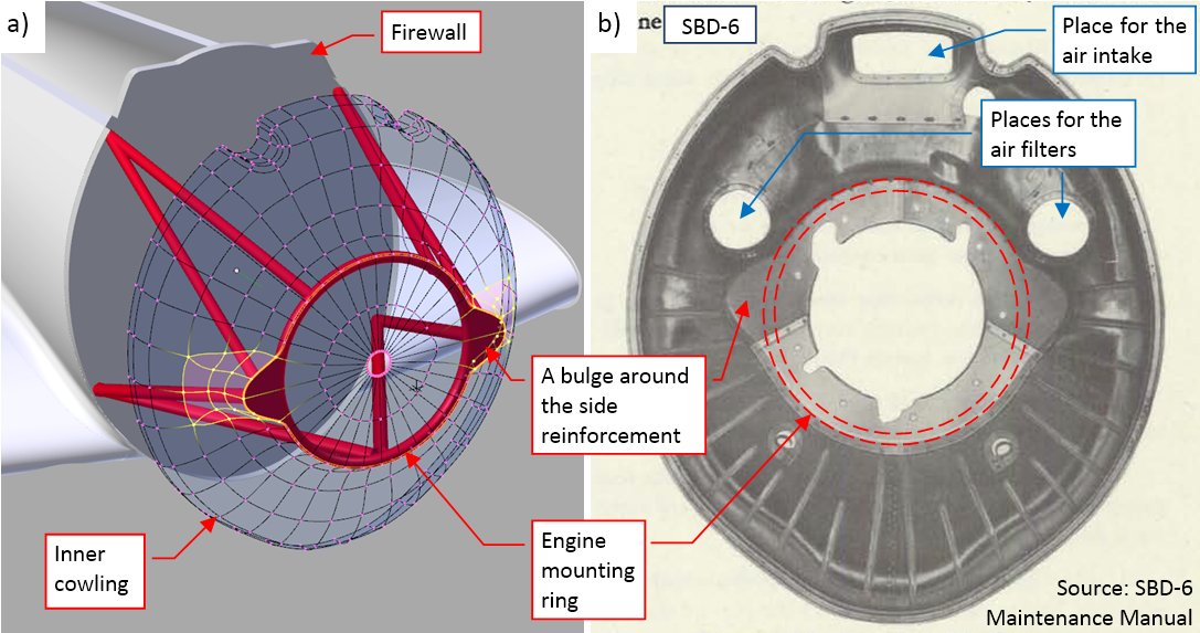
To “mount” these engines into my SBD models, I imported both scenes to the main Blender file. I defined each engine variant as a group, to facilitate placing them in the aircraft models as the group instances. I also added the firewall bulkhead and updated the shape of the cowling behind the cylinder row. (I will refer to this piece as the “inner cowling”). So far I did not especially care for the shape of its central part, hidden below the NACA ring. Now I updated it for the real size and shape of the engine mounting ring (Figure 93‑1a):

0093-01
Figure 93-1 Mounting frame details

Continue reading Mounting the Engine

Updating the SBD-5 Model

I continue updating the Dauntless versions that I am building in parallel to the basic SBD-3. In the previous post I updated the one important element of the SBD-5 model: its propeller (SBD-3 used an older version of the Hamilton Standard propeller). In this post I will continue this update.

While I already recreated the SBD-5 NACA cowling (see Figure 46-8 in this post), now it is time to adapt the panels behind it. I started by copying the corresponding cowling from the SBD-3. When it appeared in the place, I discovered a 1” gap between this cowling and the SBD-5 inner cowling panel (Figure 56‑1a):

0056-01
Figure 56-1 Fitting the rear cowling from the SBD-3 into SBD-5

Continue reading Updating the SBD-5 Model

Updating the Model of the SBD-1

As I described it in one of my previous posts, in parallel to the SBD-3 I build a SBD-1 model and a SBD-5 model. They are in the same Blender file, but in separate scenes. Since I completed the SBD-3 model for this project stage, now it is time to take care of these other versions. These models share all the common objects with the SBD-3, so I have to recreate a few different details. I already modified their NACA cowlings. In this post I will update the SBD-1, because there is just a single remaining difference: the ventilation slot in the side panel of the engine cowling.

The SBD-3 had this slot much wider than the SBD-1 and SBD-2 (Figure 54‑1):

0054-01
Figure 54-1 Comparison of the ventilation slots in the SBD-3 and the earlier versions

(I used here an archival photo of the SBD-2, because it had the same side cowling as the SBD-1. There were only 57 SBD-1s ever built, so the photos of this version are not as numerous as the later ones).

Continue reading Updating the Model of the SBD-1

Modeling the Upper Cowling of the Fuselage

In this post I will form the fuselage panels in the front of the windscreen. In the SBD there were two hinged cowlings, split in the middle. They allowed for quick and easy access to the M2 gun breeches and the internal cabling behind the instrument panels (Figure 49‑1):

0049-01
Figure 49-1 The hinged cowling in the front of the windscreen

The parts of the fuselage around the cockpit are always tricky to model. It especially applies to the panel around the windscreen. When you obtain the intersection edge of these two objects, it can reveal every error in the windscreen or the fuselage shape.

Continue reading Modeling the Upper Cowling of the Fuselage

Modeling the Rear Part of the Engine Cowling

In this post I will create the next section of the engine cowling. I copied its forward edge from the rear edge of the inner cowling panel. Then I extruded it toward the firewall (Figure 48‑1):

0048-01
Figure 48-1 Initial shape of the engine cowling behind the NACA ring

I am going to split this object into individual panels, thus I already marked their future edges as “sharp” (as you can see in the figure above). It allowed me to preserve continuity of the tangent directions around these future panel borders from the very beginning.

Continue reading Modeling the Rear Part of the Engine Cowling

The Old-Fashioned Curves of the SBD Engine Cowling

This relatively short post contains a digression about the aircraft shape. It was sparked by a suggestion that I received. Some time ago Alan from SOARING Simulator.com pointed me that the SBD NACA cowling was not as smooth as in my model (thanks, Alan!). He suggested that its contour was created from a combination of two or three arcs and a straight segment (Figure 47‑1):

0047-01
Figure 47-1 A different concept of the NACA cowling contour

Continue reading The Old-Fashioned Curves of the SBD Engine Cowling

Engine Cowling Details

In this post I will finish the engine cowling of the Dauntless (of course, for this stage of the project). In the previous posts I formed its outer panels. In the case of the air-cooled radial engines like the one used in the SBD, there is always another, inner panel: the central part of the cowling. It is located behind the cylinders and exhaust stacks. In the classic arrangement of the NACA cowling it is nearly invisible. In the SBD-1..-4 you could see only its outer rim. That’s why I had to use all available pictures of the Dauntless engine maintenance or the wrecks, to learn about its general shape (Figure 46‑1):

0046-01
Figure 46-1 The central cowling panel, behind the engine

This panel had two variants. The first one (let’s call it “flat”) is visible on the photo above. It was used in the SBD-1..-4. In the SBD-5 and -6 the engine was shifted forward by 4”, so the central panel became a little bit longer (“deeper”).

Continue reading Engine Cowling Details