In my previous posts (published in May and June) I focused on the cylinder. I think that it is the most difficult part of every air-cooled engine. Since that time I have made a significant progress, which I will report during nearest three weeks.
Let’s start with the rear section of the crankcase (behind the cylinders). Do you know how difficult is to find a decent photo of this area? The original pictures from the “Cyclone” manual are of moderate quality (Figure 88‑1a):

The modern photo (Figure 88‑1b) reveals more details. In general, it looks that the rear part of the crankcase is formed from two cylindrical segments. The intake pipes extend from the first (i.e. forward) of these segments. (There is a centrifugal supercharger inside). The upper part of the last segment contains rectangular air scoop, which also provides the mounting points for the carburetor (Figure 88‑1b). The rear wall of this segment forms the base for various auxiliary aggregates: magnetos, oil pump, starter, etc. As you can see in Figure 88‑1b), aggregates from the R-1820 exposed in the Pima Air Museum differ from the manual photo (Figure 88‑1a). I think that such equipment could be used in the B-17s. On this photo I also finally determined an important feature of the R-1820 geometry: its mounting points. (They are dimensioned on the installation drawings, but I had to find them among all these nuts and bolts that you can see on the crankcase).
I think that this rear part of this engine is much more complex than the forward section. Fortunately, it is invisible in my model (I am not going to open the engine cowling panels, at least not at this stage of the project). Thus I recreated them just as placeholder “blocks” (Figure 88‑2). In this simplified form they will allow me to determine the details of the SBD engine cowling geometry:

Once I saw these details on the photos, I was able to properly interpret the original installation drawings from the Curtiss-Wright manual. I recreated in the simplified form the intake pipe base (Figure 88‑2a). I will repeat these blocks for every cylinder. (I built this crankcase section from nine identical parts). Note the hole for the mounting bolt on the left side of the intake pipe. I just placed it there as a reminder for myself. The last crankcase section is created as a single (mirrored) part (Figure 88‑2b). I placed the simplified magnetos and oil pump on its rear wall.
In the next step I recreated there the details of the pushrod bases in the front of each cylinder (Figure 88‑3):

The rim of the forward crankcase is usually obscured by the ignition harness. I managed to find some photos that show this part. They reveal that there is a cylindrical “strip” around this rim (Figure 88‑3a), which forms the base for the pushrods. The outer diameter of this “strip” matches the rim diameter of the crankcase main section (the section that forms the cylinder bases). It is larger than the diameter of the conical part of the forward crankcase. The forward edge of this strip has characteristic “stair” shape (Figure 88‑3a). This shape repeats in the front of each cylinder. Every “step” of these “stairs” matches the base plate of one of the pushrods, or forms a bolt head base.
As I described it in the first posts about the R-1820, I formed this forward section of the crankcase using nine identical segments (clones), placed in the front of each cylinder. Thus I just had to recreate this strip in the mesh of a single segment, and Blender automatically repeated it around the crankcase rim (Figure 88‑3b). In this mesh, I used a multi-segment Bevel (Weight) modifier to round some of the newly created edges. (I have some troubles with the intersecting beveled edges, here. Finally I decided to use the Bevel modifier for the “meridian” edges, only. I created the gentler, “parallel” fillets manually, placing 3 or 4 new edges at the rim strip base).
When I reproduced the “stair” forward edge of the pushrod bases, I discovered that:
- For each cylinder, one of the pushrods is shifted forward. (This is a norm for every classic radial engine, because each of these two pushrods follows different cam. One of them uses the intake valve cam, while the other uses the exhaust valve cam);
- The pushrod bases were closer to each other than they depicted them in the original installation drawings from the Curtiss-Wright manual. (It could happen, because this was not any important, “dimensioned” element of these drawings)
I moved accordingly the pushrod bases close to each other, and then I discovered that they no longer fit their troughs in the cylinder head (Figure 88‑4a):

Fortunately, the shape of the head fins is still controlled by the surface object (via a Boolean modifier). All what I had to do was a minor adjustment of its mesh (Figure 88‑4b). Then Blender took care for the fin shapes (Figure 88‑4c).
As you can see (Figure 88‑4b, c), I also added to this model the pushrod seals and clamps. All of these details are clones (they share single mesh). These clamps will be useful in other places of this engine.
Another engine element hides among the lower cylinders (5 and 6): this is the oil sump (Figure 88‑5):

While the forward part of the oil sump appears on many photos (as in Figure 88‑5a), all what I found about its overall shape were: two pictures from the manual (Figure 88‑5b), and the side contour on one of the blueprints. However, certain features became obvious, when you place this part into the model. The recesses on its sides fit the adjacent cylinders (Figure 88‑5c), while the Y-shaped “tail” bypasses the vertical intake pipe that belongs to cylinder 5.
I formed oil sump using subdivision surfaces. To keep the shape of the front crankcase as simple as possible, I modeled the oil sump base as a separate object. Its external edges blend smoothly with the two adjacent crankcase segments. (These segments are separated along the engine centerline).
On the forward part of the oil sump you can see a prominent engine data plate. I will recreate this detail later, together with similar elements that occur in the cockpit. (They will require a separate texture).
On the opposite side of the crankcase there is a more exposed feature: propeller governor base (Figure 88‑6):
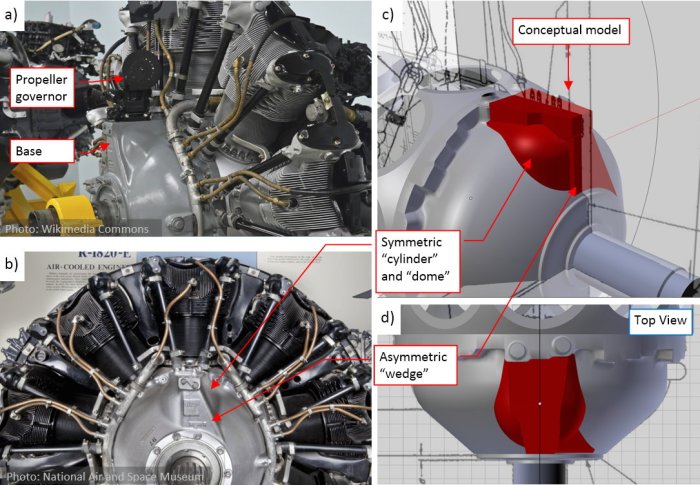
In general, its shape is a combination of symmetric cylinder and dome with an asymmetric “wedge” (Figure 88‑6b, d). To find the proper proportions of these objects, first I prepared their simplified, conceptual model (the red blocks in Figure 88‑6c, d). The most “sensitive” elements here are their intersection edges, especially on the oblique, left side of the “wedge”. I tried to obtain similar shapes of these curves to those visible on the photos. (However, in the real crankcase these edges are “soften” by the fillets. It is more difficult to determine their exact shape).
Finally, when the conceptual model was close enough to the original, I used it as the base for the final version (Figure 88‑7):

First I joined the “cylinder” and “wedge” into single object, and added fillets (multi-segment Bevel modifier) along their intersection edges (Figure 88‑7a). Then I joined the three upper segments of the forward crankcase with this propeller governor base (Figure 88‑7b). It created additional intersection edges, which I also rounded using the same Bevel (Weight) modifier. Note that I did not “smooth” this surface with a Subdivision Surface modifier: it was dense enough without it.
There was also another reason: the optimal mesh topology for the beveled edges differs from the optimal topology for the subdivision surface. For the fillets created by the multi-segment Bevel modifier, the beveled edge has to be far away from the other parallel edges. To obtain similar effect using the Subdivision Surface modifier, you have to concentrate several parallel edges close to each other. Sometimes I use a mix of these two modifiers (Bevel + Subdivision Surface). However, for the more complex shapes, like this one, this combination can create certain artifacts by its own.
The next part of the engine is the ignition harness. Figure 88‑8 shows its rear part:

In fact, this part will be invisible in the final Dauntless model. I recreated it because I just do not like to “suspend objects in the air”. Still, while fitting this engine into the airplane, the simplified versions of these invisible parts can give you a valuable hint about potential collision/intersection. The harness in the engine from the Jimmy Doolittle Air & Space Museum (Figure 88‑8a) seems to be rotated upward on the magnetos. I recreated in the reversed position (Figure 88‑8b), as in the manual (see the first photo in this post).
Note the carburetor details in Figure 88‑8a). The complexity of their shapes exceeds by a magnitude the rest of this engine. I am really glad that they are hidden under the cowling, so I do not have to recreate this “mess” of intersecting blocks and pipes, all smoothed with hundreds of fillets. (I think, that it reminds the densely packed Maya sculptures, or some instances of the modern art :)).
The manifold of the harness is a simple tube, bent along the curve that controls its shape. (I used here the Curve Deform modifier). The forward part forms a 300⁰ arc around the crankcase (Figure 88‑9):

I already placed along this manifold the bases for 18 individual spark plug cables (Figure 88‑9b). At this moment I recreated the first pair of these cables, for the topmost cylinder. Each of these two tubes has its own deforming curve. As you can see (Figure 88‑9c), I also recreated the spark plugs and the clamps that attach these cables to the pushrods. I will recreate the remaining 16 cables in the next post, when all of their cylinders will be in place. (Each of these cables will be bent along a slightly different shape). There are also four mounting brackets (Figure 88‑9d) that attach the ignition harness manifold to the crankcase.
I also recreated the deflector plates, mounted between the cylinders (Figure 88‑10):

I decided to skip (simplify) some of their features that will be less visible under the NACA cowling. Thus I omitted the bolt holes at the cylinder sides, and various small holes in some of these plates. (The purpose of the two holes visible in Figure 88‑10a) will become obvious in the next post).
Figure 88‑11 shows the current state of this R-1820 model:

I will finish it in the next post.
You can examine the model depicted above in this source *.blend file. Just remember that this is the earlier version, saved in May (before the correction of the the forward fins, which I described in my previous post).
