After “mounting” the R-1820 engines into my SBD models, I decided to recreate some details of the inner cowling (the cowling panels placed behind the cylinder row). In this post I will form the missing parts of the carburetor air ducts, hidden under the NACA ring. There are significant differences in this area between various SBD versions, which never appeared in any scale plans, or in any popular monograph of this aircraft. I think that the pictures presented below highlight these differences. They can be useful for all those scale modelers who are going to build the SBD “Dauntless” models with the engine cowlings opened. (Sometimes you can encounter such advanced pieces of work on the various scale model contests).
Let’s start with the SBD-5s (and -6s), which are better documented (because they were produced in much larger quantities). They had a dual intake system, of the filtered/non-filtered air, which I discussed it in the previous post. I already recreated the two intakes of the filtered air, placed between the engine cylinders. Now I have to create the central, direct air duct and its opening at the top of the internal cowling.
Figure 94‑1 shows the initial state of my SBD-5 model:

As you can see in Figure 94‑1b) and c), initially the carburetor protruded from the simplified shape of the internal cowling. On this stage of work I was sure that the engine is at the proper location (I matched it against the reference photo in the previous post). Thus, I concluded that the shape of the internal cowling requires an update. To determine its real form, I reviewed the available photos. Unfortunately, I have only few pictures of this obscured area (Figure 94‑2):
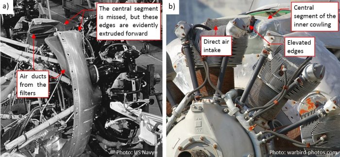
Figure 94‑2a) shows an archival photo, taken at the Douglas factory. I can see there that edges of the cowling around the central air intake are shifted forward. Unfortunately, the closing, top element of this cowling is not attached here. I can see it in Figure 94‑2b), taken from the front (which makes it less usable). On this picture I noted that the edges of the air intake are elevated above the cowling (by less than inch). It was confirmed by the pictures of the restored SBD-5 from the Pacific Aviation Museum Pearl Harbor (Figure 94‑3c, d):

In Figure 94‑3c) you can see the side contour of the inner cowling. I can see that the central area is shifted forward (marked in blue in Figure 94‑3b), and side segments around air filters are shifted back (marked in brown in Figure 94‑3b).
Figure 94‑4a) shows these faces on the updated mesh of the inner cowling:

You can also see there the top of the air duct (this is a separate object). Figure 94‑4b) shows its simple, “box-like” mesh. When both elements were in place, I used a Boolean modifier to cut out the central opening in the cowling (Figure 94‑4c).
Let’s look at the corresponding area in the earlier SBD versions. Figure 94‑5 shows the rear side of the SBD-3 engine cowling:

This case is quite different. It seems that the upper part of the inner cowling in the SBD-3 forms a “box” around the carburetor air duct. It was quite difficult to find any photo of this area taken from above (you know, in 99% cases the photographer stays below, on the ground). All what I have are the photos of the SBD-3 wreck, salvaged from Lake Michigan (Figure 94‑6):

I learned from them that this “niche” had flanges around its edges, and the air duct stood inside it like a “statue”. (There was a lot of space around this duct). The designers even formed a kind of “pedestal” at the base of this “niche” (I marked it on the right photo).
Using all this information, I reproduced this “box”/“niche” in my SBD-3 model (Figure 94‑7):

I started with a simple box, then I fitted it into the elliptical contour of the inner cowling. Finally I joined these two meshes, and rounded their edges using the Bevel (Weight) modifier. I also extruded the flange around its rear edge.
I also tried to determine the shape of the air duct. In this case the only available references were the photos of the SBD wrecks (Figure 94‑8):

It seems that this part of the air duct had a “jug-like” shape. Its upper edges fitted the horizontal air duct mounted in the NACA cowling. (That’s why the forward edge of this intake is lowered a little – just as the bottom of the air duct in the NACA ring).
Figure 94‑9 shows my attempt to recreate this part in the SBD-3 model:

I had some doubts about the forward edge of the upper cowling that overlaps the flange behind the air intake. Finally, I wrapped it around the topmost edge of the “niche” (see Figure 94‑9b). I also improved the shape of the “pedestal” in the inner cowling. (It covers the front section of the carburetor – see Figure 94‑9a). I assumed that the air intake looked like that in the SBD-2, -3 and -4, because they share the same air duct design.
I have not any reference materials about the internal air duct in the SBD-1. I assumed identical shape of the inner cowling as in the SBD-2, -3, and -4. Figure 94‑10 shows other assumptions:

I assumed that the general shape of the internal, vertical air duct segment was as in the later versions. The only difference are its simpler upper edges, fitting the opening in the NACA cowling. (There was no “lower” part of the external air duct under the NACA cowling, which you can see in the SBD-2, -3 and -4).
In the next post I will add the last details to the inner cowling, finishing my work on the engine compartment.
You can download the model presented in this post from this source *.blend file. To reduce its size, it is stripped from the texture images. (During the last year the size of this source file has significantly increased, reaching 40 MB in the compressed form. More than 35MB of this amount is used by the texture images. Thus, I will preserve the texture images in the source file only when they are relevant to the topic of the post)
