In the previous post I finally identified Curtiss layout sketch L-10202 as description of the XP-40 geometry, as it was in February 1940. In that time Curtiss was finishing preparations for serial production of the P-40. (The first P-40 from this batch was accepted by USAAC in April 1940). This final variant of the XP-40 resembled the serial P-40-cu, except the tail wheel cover and rear glass frames, “inherited” from the P-36. However, the archival photos revealed minor differences between engine cowlings of these aircraft: the serial P-40 had longer spinner and deeper radiator cover.
It seems that all the original drawings and sketches of the early P-40s that I collected from the AirCorps Library resources describe the XP-40. Thus, first I will prepare the XP-40 side view using this original documentation. Then I will draw a P-40B side contour, using these XP-40 lines and available P-40-cu/B/C photos.
As I showed in one of previous posts, the XP-40 sketches are not only rare, but also in poor shape:

Their lines are fading into background, so you can see only fragments of the original blueprints. Frankly speaking, it was often hard to identify what part they are depicting. Thus, first I had to outline their key contours and reference axes in a separate Inkscape drawing, making them more visible:
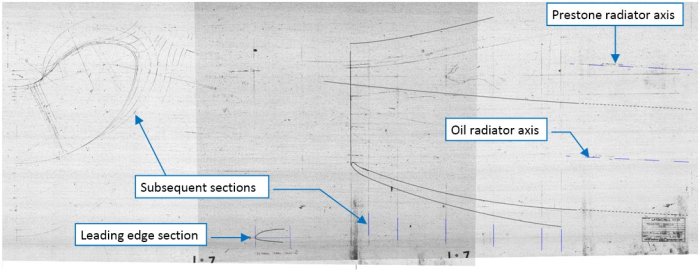
Then I fitted such enhanced drawings into my “main assembly”. They allowed me to recreate the contours of the cooler inner ducts. You can see the result in the picture below:

The blue component in the color of these lines determines how much they are based on the information from the photos. (This means that the red lines are fully confirmed by the blueprints, purple lines – partially confirmed by the blueprints, while the pure blue lines are based solely on the photos).
The L-10202 cowling assembly layout does not provide contours of the carburetor air scoop and the gun fairings, located on the top of the P-40 engine cowling. Fortunately, I have found sketches of their key parts among AirCorps Library files:

Both drawings contain not only the key dimensions, but also references to the engine cowling stations, which allowed me to determine their X coordinates on my drawing. In addition, the carburetor air scoop contains reference to the cowling upper contour, which determines its vertical location (its Y coordinate on my drawing). To find similar coordinate for the gun fairing, I had to find the position of the gun barrel axis. For this purpose, I used the P-36/Hawk 75 drawings (as you remember, the P-36 and the early P-40s shared the same fuselage behind the firewall. This means identical gun barrel axes). Below you can see the gun mount blueprint from an export Hawk 75.
(I also have similar drawing of the P-36, showing that the barrel axes of the the 0.5” and 0.3” guns are symmetric. However, its lines are fading into background, thus I am showing here the more readable of these two scans):

The gun barrel axis location is specified in the front view. From this blueprint I learned that it was placed 22” over the fuselage reference line. Using this information, I could precisely place the gun fairing reinforcement from SK-2605 in my drawing.
Looking at the picture above I also noted that in this Hawk 75 (as well as in the P-36) the space separated by wing spar #1 and #2 and the fuselage ribs was used as the container for the used cartridge cases (for re-using). Such a frugality was common in the pre-war USAAC (and in some air forces of other countries). In this front view you can see at the bottom of the fuselage the case ejector doors (in the open position). You can also encounter similar doors in the P-40-cu. They could be bolted, if you wanted to bring back all the cases to the airfield. In the P-40B/C they removed these doors. I suppose that inside the wing they also added a “pass-through” segment of the case ejector duct, but I am not sure.
In the drawing below I drew the details of the P-40 upper cowling using the SK-2603 and SK-2605 sketches. They allowed me to determine the location and size of their fairings:

As you can see in the picture above, I also speculated about the shape of the case ejection duct in the P-40B/C wings.
The next missing element was the location of the engine exhaust stacks and their opening. On my photos this detail is always shifted vertically and horizontally, following the camera position, which was never ideally “inline” with the fuselage axis. (It could not be). Thus, to “pin” more precisely this opening, I used the P-40-cu engine mount drawing (drawing no. 87-22-001):

I do not have any decent drawing of the Allison V-1710-C engine, used in the early P-40s. Instead I used here the contours of its later variant (V-1710-F), from the P-40D. (They used different gear boxes, but it seems that their key dimensions and exhaust stacks locations were identical). I carefully “attached” this engine profile to the bolts visible in the P-40-cu engine mount. Finally, I could use this picture for adjusting the location of the exhaust stacks opening contour, which I prepared according the photos. (As you can see, in my drawing I outlined this opening in purple, which means that this is a “partially confirmed” element).
I discovered that the front side view in the main L-10202 layout also contains some faded lines which, after matching with the photo, occurred to be the split lines of the cowling panels:

L-10202 indicates that these lines run across the cowling in the radial directions, as I marked in the picture above. What is interesting, they fit the photos of the productive P-40-cu/B/C. In the XP-40 the seam line above exhaust stacks runs a little bit higher than in this layout. (Was it an effect of a tooling problem?)
There were some interesting details around the spinner. I highlighted them in the picture below, which compares the early and late variants of the “long nose Hawks”:

Note that the spinner rear edge overlaps the engine cowling. Such a solution was used in all P-40 versions. (I think that it could minimally reduce the aircraft drag). In the pictures above you can also see that the shapes of the cutouts in the spinner around the propeller blades differ between these two aircraft. In the P-40-cu the propeller blade base cross section is circular, so its cutout in the spinner has a circular shape. Similar opening in this AVG “Tomahawk” IIA from the photo above seems to have an oval shape. In Dana Bell’s “Aircraft Pictorial #5” book I have found a mention that the P-40-cu used the hollowed steel propeller blades. Shortages of these blades during further production of the P-40B/Tomahawks forced Curtiss to use a substitute: solid aluminum blades, which were somewhat heavier. Maybe this AVG aircraft used such an aluminum propeller?
In the P-40-cu photo you can see the long blast tubes. They occurred to be too long: engine vibrations and other random circumstances could deform these tubes during flight. In some extreme cases, the fired rounds could shatter ends of these tubes. In response, Curtiss decided to them close to their fairings, as you can see in the AVG aircraft, and reinforce the cowling panels in the front to withstand the blasts. This change was also retrofitted to the previously produced P-40s.
Below you can see my sketch of the XP-40 spinner:

The L-10202 layout marks the propeller blade axes plane at 99 11/16” from the firewall. (BTW: the general assembly drawings of the early XP-40s, from fall 1938, placed this plane at 99”. However, that initial variant used a different, shorter spinner). I have also found a drawing of the engine cowling bulkhead (drawing no. 75-29-834). This scan was in a poor shape, but it allowed me to determine the precise location and size of this disc. However, none of these drawings does provide the location of the spinner rear edge. I had to determine its X coordinate using photos (that’s why I drew this contour in blue).
Note that in the previous XP-40 picture I drew the gun blast tubes, which is simply wrong. (The XP-40 was not armed in the photo from February 1940). In this picture I corrected this mistake.
I also found faded blueprints of the spinner assembly and the front bulkhead (drawing no 75-42-803 and 75-42-823). The assembly, dated from 1939, seems to describe a shorter, non-overlapping spinner. (It shows a 5/8” wide gap between the spinner rear edge and the fuselage cowling. I suppose that the later spinner variant was extended by about 1” behind the base bulkhead, covering this gap and a thin strip of the cowling). From this assembly drawing I also copied the circular contour of the propeller blade opening.
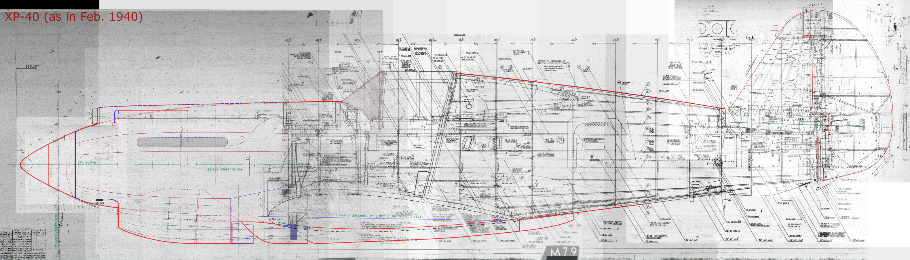
Picture below shows the resulting XP-40 profile (you can download its high-res version from here):

As I discovered in the previous post, the serial P-40s had longer spinner and deeper cowling around the radiators. In the Allison-powered aircraft there were two radiators of the engine cooling liquid (in Curtiss docs it appears under its commercial name: “Prestone”) and single oil radiator. In the photos of the cowling details (Figure 102‑9) you can see that these coolers had simple cylindrical shape. I have found two blueprints of their mounting brackets: one for the XP-40, another for the “short nose” P-40E. While the diameter of the oil radiator remains identical in both drawings (11.12“), the Prestone radiators in the XP-40 are smaller (13.12” in diameter) than their counterparts from the P-40E (14.63”). I compared the proportions of the oil/Prestone coolers diameters in various photos of P-40-cu/B/C and came to conclusion that most probably their Prestone radiators were as large as in the P-40E. It seems that the cowling from L-10202 layout was wide enough to fit these larger coolers. The vertical distance between the axes of the oil and Prestone radiators increased from 9.5” in the XP-40 to 10” in the P-40. Assuming that the upper part of the cooler air duct remained intact, I had to lower the axis of the Prestone radiator by 0.755”. In the result, the axis of the P-40 oil radiator occurred 1.25” lower (0.755” + 0.5”) than in the XP-40. Such a configuration fits the archival photos. (In the picture below I marked the XP-40 radiator axes in black and the P-40 radiator axes in white):

Matching the aircraft contour from an orthogonal side view to a perspective-deformed photo is never easy or error free, especially in the case of the photos made with the typical lens length (about 35mm). In the case of the “Tomahawk” IIA photo above, the details on the upper part of the cowling seems to be shifted up, and the spinner is a little bit longer than it was. However, it seems that the area around the cowl flaps and the landing gear struts is not deformed (it was in the center of the original photo). Basing on these assumptions and the sketch of the XP-40 duct I drew the P-40 contours (in blue, because they are based solely on the photos). Note that the part of the cooler air scoop is still in red – because it was lowered by about 0.5”, but did not move from its original station (74” from the firewall). The complete arc of the cowling flaps was lowered by 1.2”.
Of course, I checked these contours against several other historical photos, to reduce the error margin, unavoidable in such a method.
I also compared this contour with the long-lens photo of the restored P-40B:

In general, they match each other. However, as I learned from the Classic Wings article, the restoration team of this aircraft did not have any original drawings of the P-40B engine cowling. They restored it using multiple photos of another restored P-40. In general, it seems that such an approach was quite accurate, except the rear cowling segment, located behind the radiator (see the picture above): it is definitely too flat.
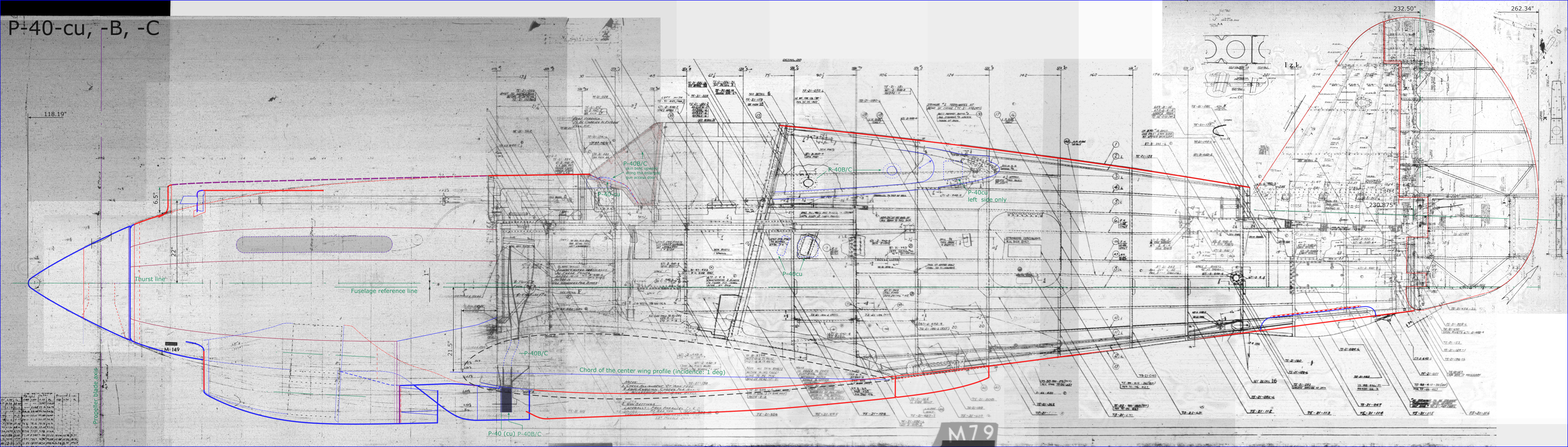
Figure 102‑14 shows the resulting contours of the P-40B engine cowling:

In Figure 102‑15 you can finally see the complete P-40B side contour:

Use this link to get the high-resolution version of the picture above. You can use it as a reference for your model. Note also that the blue lines in this drawing are still based solely on the photos (i.e. they are not confirmed by the blueprints). This is due the lack of the documentation of this P-40 version. In the case of the “short nose” P-40D or later versions, as well as in the Pratt-Whitney powered variants of the P-36, you would see all (or nearly all) lines in the “confirmed” red color.
Of course, this is not a complete side view: I prepared this image for my own purposes, as the reference for building a precise 3D model of the P-40B in Blender. This work allowed me to identify which of the collected Curtiss drawings are useful, but I also learned about their limitations.
Thinking about further steps I realized that this “classic” approach:
- Create from the original assembly blueprint a 2D reference drawing (I did it here);
- Create from the 2D reference drawings a 3D model (I am going to do it);
is not optimal.
For example: the contours of a real object are a mathematical abstraction: infinitely thin lines. On the other hand, in a 2D drawing I always have to draw them using lines of a non-zero thickness. I can “work around” this issue by assuming that the precise contour lies on the outer side of its outline. However, inside these thick lines I could inadvertently create some small, but important, misalignments and discontinuities.
I started to think that this work on a 2D side view was just an “reconnaissance survey” of the Curtiss documentation. So far I used only fraction of the available information: most of the layout drawings provide complete 3D coordinates. For this side view I used only two rows from their ordinates tables, (the rows that describe the upper and lower contours). For the top / bottom 2D views I would also use just a single row from these tables! (The row that describes the symmetric side contour). Of course, I could also trace on the reference drawings additional lines “in between” these top and side contours. However, I am afraid that they would not be as precise as in the source ordinates table, because I would have to trace the same line twice, in each view. Everybody makes errors, but these mistakes would not be evident when they are split between two 2D views. Much better idea is to use the coordinates provided by the ordinate tables for creating a kind of 3D “reference grids” in Blender. Then I will use them for building the ultimate model. Such a “reference grid” of the fuselage would contain contours of its cross-sections at selected stations. Similarly, the wing “reference grid” would combine contours of the key ribs, webs (spars), and the wing tip outline.
In Blender 2.7 (and earlier versions) the limited system of 20 “flat” layers was an obstacle in effective organizing the resulting model surfaces, their 3D references and the multiple source blueprints. Fortunately, the new hierarchical collection system in Blender 2.8 finally allows for such a kind of work.

2 thoughts on “Recreating the P-40B Engine Cowling (Side Contour)”