Before you organize the original blueprints of an aircraft, collect as many reference photos as possible, and familiarize yourself with the aircraft shape, main assemblies and – especially – their joints. You will need all this knowledge to quickly recognize the drawings you need. About 60% of the original blueprints depict various small, internal details (tubes, brackets, plates, etc.) which are necessary only when you would like to build a real, flying airplane.
To select a useful subset of these blueprints, I had to review all the drawings in the microfilm set, and copy some of them into one of the target folders:

You can do such a “review” using two File Explorer windows: one for the source drawing list (of course with the preview pane), and the other for the target folder.
To quickly find any of the selected drawings during the further work, I organized them into a tree-like folder structure. As you can see in the picture above, each target folder represents an aircraft assembly. Initially there are just three: Empennage, Fuselage and Wing. Then each of these main assemblies (folders) splits into subassemblies. For example – Empennage contains separate subdirectories named Fin, Rudder, Stabilizer and Elevator. I copied the interesting files from the source list into the appropriate subassembly directory. Then I renamed each of these copied files, giving it a descriptive name, and an ordinal number (for example – “Assembly-01”). The ordinal number is needed, because you can often encounter several variants of the same drawing, coming from various versions of this aircraft. If I encountered another assembly drawing of the stabilizer, I would copy it into this directory and name “Assembly-02”. Note that these file names are relatively simple, because the tree-like folder structure provides the necessary context (I know, that this “Assembly-01” file contains the drawing of the stabilizer assembly, because it is located in the Empennage\Stabilizer\ path). In the root folder (Empennage) I can place drawings that are related to whole assembly, like the empennage erection scheme, which describes how to mount the fin to the stabilizer and the stabilizer to the fuselage.
Of course, the structure of these folders and subfolders reflects the structure of the particular aircraft. For example, in the case of the Soviet La-5 fighter the fin is an integral part of the fuselage, thus there would be no separate “Fin” directory.
In my case the I used the AirCorps Library site as the source of the blueprints. I did it, because it already grouped the original drawings into categories, based on their unique numbers:
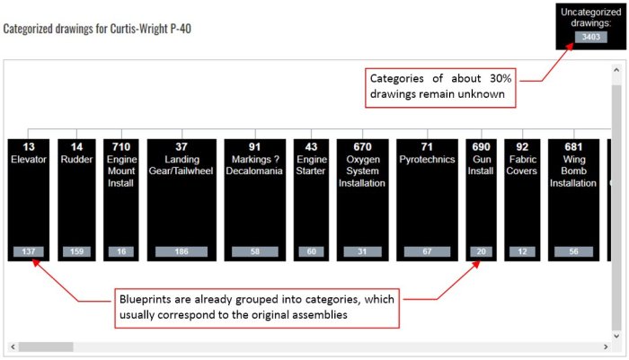
In practice, drawing numbers of each manufacturer contain a segment which describes the category (assembly) of the depicted part. Of course, every manufacturer used its own rules for this purpose. Sometimes these rules are difficult to identify. For example, the P-39(/P-63) drawings in AirCorps library are categorized by first three digits, but these categories are not named. You have to use the name index of the original microfilm (provided on the same page) to find the key assembly drawings of these aircraft.
Fortunately for me, in the case of the P-40 AirCorps Library properly identified the middle section of the Curtiss drawing number as the assembly id, and even provided appropriate assembly names. In most cases these categories are more detailed than I need. For example: I used just the single assembly drawing from the “Engine Mount Install” category, and skipped the entire “Engine Starter” category. However, note the large number of the “Uncategorized” blueprints: 3403! I reviewed this group as the last one. First I tried to complete the assemblies using the drawings from the identified categories. Then I learned, which blueprints were missing, and looked for them in this “unidentified” category.
I reviewed the AirCorps Library blueprints using their web page result list, and “printed to PDF” the drawings that I selected. (For details, see the last part of my previous post, Figure 97‑12 … Figure 97‑15). I saved these PDFs into corresponding target folders.
In the figure below I am showing an example of such a “target” directory, which describes a single subassembly: the stabilizer. As you can see, I chosen just few drawings that describe this part: except the general assembly that you can see in Figure 98‑1, I also chosen the blueprint of its ribs:

(The last rib, located at the stabilizer tip, is documented in another drawing, which I named “Ribs-02”). Note that each of these AirCorps Library pictures contains a large drawing number. I can use it for re-checking the source list. (Sometimes this information allowed me to skip duplicates).
Another stabilizer drawing – “Webs-01” – describes the stabilizer webs (spars):

As you can see, I also selected two important details: elevator hinges. (In the P-40 they are visible in the small openings in the elevator leading edge).
Some drawings were re-used between subsequent aircraft types. In this case the detail drawing of the stabilizer tip edge is located in the parallel folder tree of the P-36:

This edge was a simple “V” – shaped beam, bent along an arc. It was identical in the P-36 and P-40.
As I mentioned in previous post, the microfilm scanned by AirCorps Library contains mixed drawings of the P-40, YP-37 and P-36. I skipped the YP-37, but for the P-36 I prepared a parallel folder structure. Fortunately, you can recognize each aircraft type by the prefix of its drawing number: “75” is for the P-36, “81” is for the YP-37, and “87” is for the P-40.
Of course, the more complex assemblies, like Fuselage, contain more drawings:

I created some of the subassembly folders (for example: Antenna) just because the number of the antenna drawings exceeded seven (there were several variations of the antenna mast). Note that there are many assembly drawings (“Assembly-02”, “Assembly-03”, and so on). Curtiss engineers had to prepare a new one for each of the P-40 versions (D, E, F, K, M, L, N). I even created a separate subfolder for the variants with extended fuselage (later variants of the P-40F, K, M, L and all of the P-40N).
When a blueprint spans over several microfilm frames, I saved them with additional “a”, “b”, “c” suffix:

In general, in this Fuselage folder I placed the assembly drawing, skeleton drawing, and the drawings of each bulkhead. (Usually such a bulkhead is also built of many components, thus in the original documentation they are also referred as the assembly drawings). Sometimes there are more than one drawing for a bulkhead (especially the most complex one: the firewall). I skipped the lengthwise stringers, because they are simple L-shaped beams, slightly bent between subsequent bulkheads. For similar reason I did not copy from the source list the fuselage longeron drawings. I also selected some important details – for example the wing attachment fittings. (although they were hidden behind the fairings, they were visible from within the cockpit). There are separate subfolders for the spinner, engine cowling, cockpit, and tailwheel. The engine cowling had several variants, thus I created additional subfolder: one for the “long nose Hawks”, i.e. P-40cu, P-40B and C, one for the “short nose Hawks” (P-40D and later versions), which in turn splits into the cowlings of the Allison-powered (D, E, K, M, N) and Merlin-powered (F, M) aircraft.
Similarly, in the Wing folder I placed the assembly drawings, skeleton scheme, and drawings of the ribs and webs. There are also separate subfolders for the flaps, ailerons, wingtip, fuselage fairings, keel (the “continuation of the fuselage” under the wing, specific for the P-40), guns, landing gear and its fairing.
Ultimately I selected about 900 P-40 drawings, organized into 36 folders and subfolders. There are also about 450 P-36 drawings, organized into 23 folders and subfolders. However, I realized that the documentation from this microfilm set is not complete: I could not find some important drawings that are listed on the assembly blueprints.
What’s more, I found just a few of the “long nose Hawk” (P-40-cu/B/C) drawings. For example, the largest P-40/B/C part that I identified is the Allison-1710 C15 engine mount:

The rest of the identified “long nose Hawk” blueprints describes the XP-40 prototype. Judging by the drawing numbers, the XP-40 was treated just as another P-36 variant: these numbers have “75” prefix and “8” in the fifth digit. For example – you can find in the AirCorps Library the drawing of the XP-40 radiators support under number: 75-50-858:

Note the hardly visible, thin lines of this drawing. In some areas they disappear into the background. This is the rule, not exception: most of the XP-40 drawings is even less readable!
There are also many XP-40 drawings where the only recognizable element is the title block:
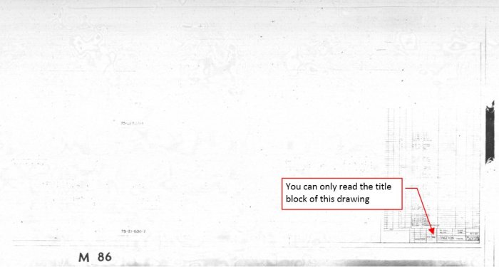
Abut 25% of the scarce XP-40 blueprints is unreadable! It seems that because of the poor contrast of the original drawings and improper microfilm camera settings these pieces of information are lost forever.
This is a serious problem. I started this project to improve my P-40B model. I can use the blueprints of the P-36 four-gun wings and the P-36 fuselage (the part behind the firewall) as the first approximation of the P-40B airframe. They can be augmented by some details from the P-40D/E drawings: the “keel” under the center wing, the flat, larger tailwheel cover, larger main wheels and their simpler fairings. However, I desperately needed the geometry data of the unique P-40/B/C engine cowling!
It seems that I am not the first one who encountered this problem. In the issue 80 of the “Classic Wings” magazine I found an article about a P-40B restoration made recently by AvSpecs team. Because of the lack of any documentation, they restored the engine compartment using just the photos of another restored P-40! (See the marked fragment):
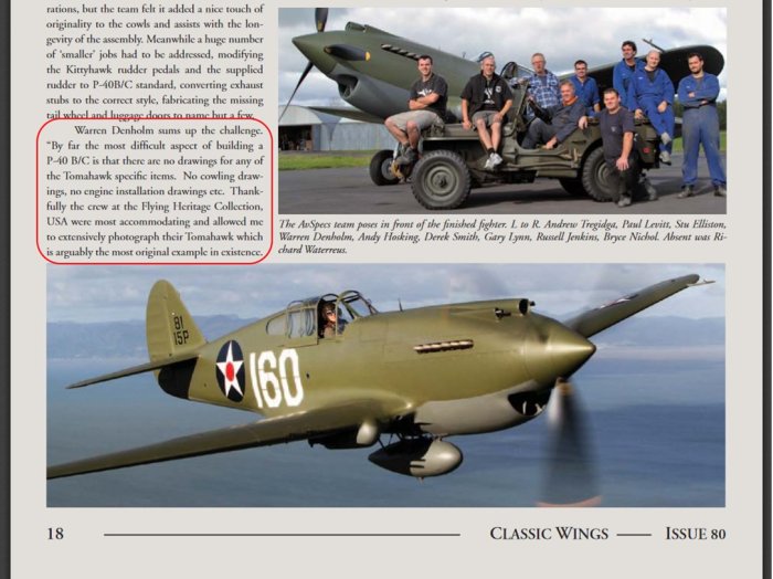
In such a case there is a chance that they are also copied some non-original details, introduced during restoration of this P-40B from the Flying Heritage Collection.
Having all this in mind, I started to review the 3400 uncategorized drawings from the AirCorps Library. First I found there an additional P-36 category, omitted probably by a mistake: drawings 75-28-XXX that describe the NACA ring of the Double Wasp engine. Of course, they allowed me to fill this gap in the P-36 documentation, but it was not my main concern. The other drawings in this “uncategorized” list seemed to belong to the Y1P-36 (drawing no. prefix: 85-* and 99-*), XP-37 (prefixes: 84-* and 90-*), and P-40F (prefix: 96-*). There were also special classes of “layout” drawings (prefix: “L”), working sketches (prefix: “SK”), and design proposals (prefix: “P”).
I have found there some XP-40 sketches, like this one (SK-2698):

In the title block of this sketch I could read “Cooler Duct – Rear”. Looking close at these thin, vanishing lines, I was able to recognize the rear view and side view. However, between October 1938 and April 1940 the XP-40 engine cooling system was redesigned four times, and only the last of these modifications, made after December 1939, match precisely the ultimate shape of the P-40/B/C cooler. I was not sure if this drawing depicts this last update.
I also stumbled upon a layout sketch (number: L-10202). In its title block you can read “Basic Cowl Lines”. However, the aircraft type is unreadable, as well as the dates (the first date could be “1/6/39” and the last date “6/7/…”, but I am not sure):

Looking at this side profile with relatively small air scoop “chin” and missing cooler duct outlet, I thought that it depicts the “middle” arrangement of the XP-40, from January 1939. However, later I noticed that the shape of the air scoop in the front view seems to be much larger, and it looks familiar – like those in the P-40B/C! (None of the earlier XP-40 variants had the scoop divided into three separate air ducts, like the one you can see in this drawing). This sketch also contains a partially readable ordinates table. It provides numerical coordinates of the engine cowling, expressed in a cylindrical coordinate system:

The distances along the thrust line are measured from the firewall. All dimensions are in inches. Looking at this table I realized that its left side describes the “smooth” body of the initial engine cowling (as in the original XP-40 configuration, with the box-like radiator cover placed behind the wing). The appendix on the right side of the ordinates table describes an update (the final version?), with the cooler duct placed under the engine. This drawing simply skips the outlet of this cooler air duct (because it is depicted in another sketch?). It also lacks the carburetor air scoop and gun covers, placed on top of the cowling. However, maybe this is just a “conceptual” drawing, which did not need to take these details into account?
I decided to fit the shape described in this sketch to the P-36 fuselage, and check if such a combination match the P-40 photos. Maybe this is the real geometry of the P-40/B/C engine cowling? I will discuss the results in the next post.

3 thoughts on “How I Organized Original Blueprints of an Aircraft”