In this post I describe a break in the modeling that I made this week, because I had to fix my reference photos before the further work. The reason for this fixing was simple: the NACA cowling of my model did fit only the long-lens photos. For the further work I needed more information. This information was available in the high-resolution photos made by the Pacific Aviation Museum Pearl Harbor. However, they are slightly distorted.
In the ‘mathematically ideal perspective’ calculated for the computer cameras all of the straight lines remains straight. Unfortunately, the real-world camera lens can slightly deform (bend) the straight contours. This is so-called ‘barrel’ (or ‘cushion’) distortion of a photo. Unless you are using a panoramic lens, this deformation is hardly noticeable for the naked eye. Unfortunately, these differences become evident when you place a photo behind a 3D model, projected by a computer camera.
In case of reference photos that I used to verify my SBD Dauntless, the differences caused by the barrel distortion are visible around the forward part of the engine cowling (Figure 42‑1):

It is really difficult to find the precise shape of this airplane on such a deformed photo. Thus I started searching the Internet for a method that would allow me to revert this deformation. First I encountered some advanced tools, like Hugin software. However, it seems to require series of similar photos to make a really improved picture. None of my single photos met this criteria.
On the Internet I also found some general scientific/engineering papers about the barrel distortion, as well as the tutorials how to fix it (for the architectural visualizations). They advised to use some originally straight contours/lines visible on the photo to estimate the image distortion. Indeed, for the photos as above, I can use the splits between airstrip slabs as such a reference (Figure 42‑2):

I marked these lines on the photo above using dashed line. To see better their deformation, I draw along them straight lines, in blue. Note that these straight lines are tangent to the dashed lines on the left side of this picture. On the right side of this picture you can see maximum deformation of these split lines. This is the evidence of the barrel distortion.
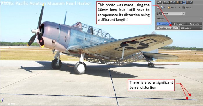
I tried to reverse barrel deformation of this image using these split lines as indicators. I used a simple Lens Distortion filter from GIMP 2-D graphic program. The idea was that when I apply a deformation that makes these lines straight. Maybe such an operation will reverse the whole barrel distortion in this photo?
Figure 42‑3 shows the Lens Distortion filter dialog window (GIMP), which I used to find the proper “reverse deformation” for this photo:

As you can see I used only the first (Main) parameter of this filter. I decreased its value until the split between the airstrip slabs on the preview became straight.
Then I matched the projection of my 3D model to this photo (Figure 42‑4):

This is really a rough, approximate method, but the obtained results look really promising! Now the whole cowling fits the modified photo!
If it worked well for this picture, I tried it on another one (Figure 42‑5):

The SBD fuselage spans over the whole length of this photo, thus the barrel distortion is more visible here. You can see it in the fin and the last bulkhead (see Figure 42‑5a), as well as in the engine cowling (see Figure 42‑5b). However, the contour of the hangar roof was a great reference for the reverse deformation. What’s more, the GIMP dialog windows preserves the last used parameters. Thus I even did not have to adjust again the Lens Deformation filter! The same value of Main = -6.8 (as set in Figure 42‑3) made the hangar roof ideally straight. Both photos come from the same source, and their EXIF data reveal that they were made by the same camera. Thus I think that this deformation value is the “constant” property of this particular camera, which is repeated in each photo it made.
As you can see in Figure 42‑5, after reverting the deformation, this picture perfectly matches the 3D model over the whole length, from the cowling to the fin.
During careful examination of all the nook and crannies of the fuselage, I encountered the difference at the root of the tailplane. In my model this rib seemed little bit shorter than in the photo (Figure 42‑6a):

When all other element of this section fits the photo, such a gap means a real difference between my model and the original airplane. After some tweaks I decided that this rib was less deflected from the fuselage centerline (Figure 42‑6b). (It seems that I made wrong estimation of its angle when I sketched these drawings). In fact, this rib run in parallel to the fuselage surface. Figure 42‑6c) shows that such a modified rib fits the reference photo pretty well.
As in the science: a theory is widely accepted, when it allows you to discover something previously unknown. These updated photos allowed me to find another error in my model!
I quickly converted most of the other photos from the same air museum. Unfortunately, I encountered the limits of this simplified method, when I tried it on the photos taken from a ¾ view (Figure 42‑7):
I could not fit the model to the modified version of this photo! I had to revert to the original picture and its matching (using a slightly different lens length co compensate most of the barrel deformation).
It seems that the simple method of applying Lens Distortion deformation works only for the objects set in parallel to the picture plane.
For the consolation, I scanned again the Google image search (I have not done it for over four months). It was a fruitful idea, because I found two new reference photos, made by a long-lens (600 mm) camera. (They were published in this post from General Aviation News blog). The first of these pictures is even more banked aircraft than I have found before (Figure 42‑8):

In spite of the same Navy blue camouflage, this is a different SBD-5 from Commemorative Air Force (note its “5” side number). It allows me to verify the important details of the vertical view: the width of the fuselage or the shape of the engine cowling. As you can see, the model fits this photo pretty well. In particular, I found here the confirmation of the new deflection angle of the tailplane root rib.
Another photo is an extremely high resolution (5400 x 3600 px) picture of the same aircraft, taken during landing. It allows me to check better the side view details (Figure 42‑9):

Ultimately, on such a detailed picture I was able to find the dynamic deformation of the wing: it is slightly bent upward, so its tip is no more than an inch above its non-loaded location. The Dauntless wings were as stiff as in the fighters!
In this source *.blend file you can find one of these updated photos.
In the next post I will start to work on the NACA cowling details, using the reference objects formed in the two previous posts.

6 thoughts on “Fixing the Barrel Distortion of the Reference Photos”