In this posts I will analyze differences between my 3D model (built from 2015 to 2019) and the SBD geometry data obtained from the original documentation. Actually, I can perform such a ultimate comparison for the wing, because I found its original geometry diagram in the NASM microfilm. In previous post I used it for preparing a “reference frame” for such a verification. Results of this comparison will allow me to determine the real error range of my previous methods described in this blog, in particular – the photo-matching method.
Unfortunately, the incomplete microfilm set from NASM does not contain any other geometry diagram, so I will not be able to prepare such a precise reference frame for the SBD fuselage or empennage.
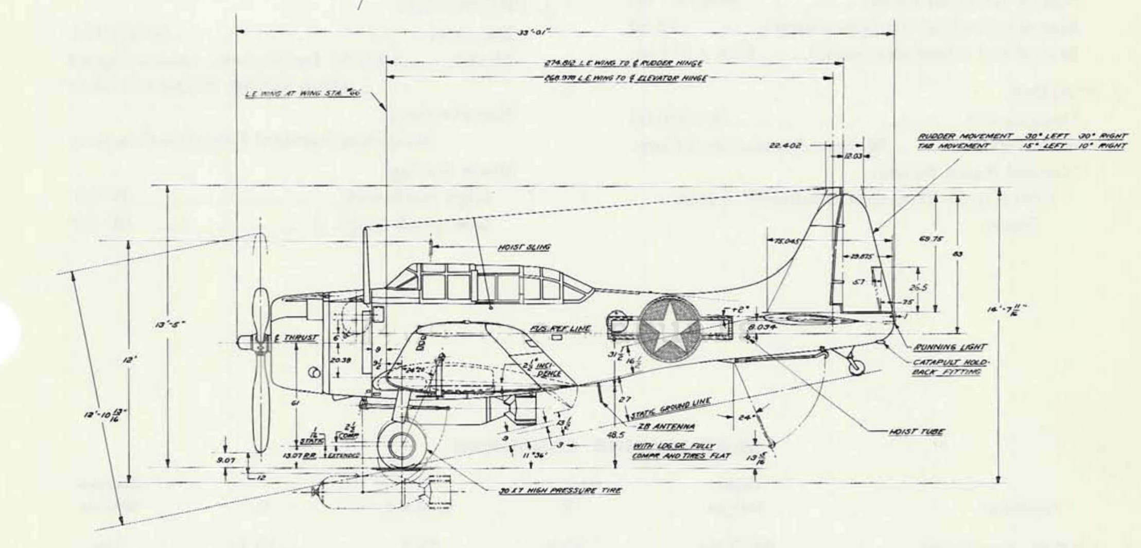
At the beginning, I identified an error in the wing location. It was determined by the position of leading edge tip of STA 66, marked as point A in the picture below:

In this post from 2015 I determined this location using the general arrangement diagram that I found in the SBD maintenance manual. As you can see above, there were issues in deciphering some of its dimensions. One of them was the distance from the thrust line to point A. I identified it as 20.38”, which means that in my model this distance from the fuselage ref line is 26.38” (6” + 20.38”).
A high-resolution scan of another arrangement diagram from Douglas microfilm (dwg no. 5120284) shows that this distance was 26.52”. (You can see this dimension in the picture above). Thus – this is the first identified error in my model, caused by a mistake in reading available drawings: 0.12”.
After re-adjusting wing position in my model, let’s examine the center wing section:

In previous post I already mentioned my wrong assumption about the 15% thickness of the outer wing section at STA 66 (i.e. at the section joints – see Figure 109-4 in that post). Now I can see the effects of this error: upper wing surface of my model is located about 0.35” above the red reference rib (i.e. above the rib created according the master diagram ordinals). As you can see, I also made minor mistakes in the leading edge shape. There is an offset of 0.15” in the top view contour, and a difference in the shape of the forward part of the wing root profile. The latter does not exceed 0.3”. Because of these differences, you can see that the original wheel bay protrudes a little from the wing leading edge of my model. In general, wing webs (spars) locations are quite precise – just the Web #2 is shifted by 0.3”.
Let’s look now at the bottom side of this wing section. Surprisingly, the Web #5 location and the radius of the trailing edge precisely match the master diagram data. However, the lower wing surface is placed 0.05” above the wing ordinates (this is a minimal difference, but still visible in this model):

I also properly identified location of the Web #1. In my model I placed the most forward (“nose”) web in a slightly different location – about 0.15” to the rear. I made the biggest error in the shape of the lower, forward part of the wing root profile: it reaches about 0.5” near the leading edge. (As I remember, I assumed this airfoil shape basing partially on fitting the main wheel, and partially on the photos). The wheel bay location and size are surprisingly close to the master diagram data: the overall error does not exceed 0.15”.
In general, the center wing section of my model matches quite well the master diagram ordinals. Of course, I will fix all these differences, but I will do it later (I describe it in another post).
Now – what about the shape of the outer wing section? I found there much greater differences:

While the aileron and flap seem to match the master diagram pretty well, there is a significant difference at the wing tip. Also, the fixed slats are shifted outward by about 1”. However, we are comparing here my original wing model (dihedral angle along trailing edge: 10.2°) with the master diagram drawing placed on the original reference plane (dihedral angle: 8.5°). In the previous post (Figure 109-15) I demonstrated that the real wing tip was 1.43” closer to the aircraft center plane than the tip depicted in this reference image. (This is because of the strange location of the reference plane in the outward wing). To fully assess these differences, I switched the current view to the projection aligned to the original, oblique reference plane of the outward wing:

Here we can see that the wingtip of my model exceeds the master diagram shape by 2”! On the other side, this is the result of two coupled errors. As you can see in this post and this post, I used the arrangement diagram from SBD maintenance manual as the primary source of the basic geometry.
In this diagram the basic trapezoid of the outer wing is described by five dimensions. I could not know that three of them are wrong! In the picture below I placed these dimensions in blue and red boxes (the wrong values are in red boxes):

In practice, this means that I unconsciously “stretched” the outer wing in my model, matching the wrong wing span. (For example – I shifted entire outboard wing section outside STA 66 by 0.8”. Such a modification did not agree with the stations diagram from the maintenance manual, but it was the only way to place the wing tip according the dimension from this arrangement drawing).
By the way: now I can see another error in the drawing above. Note the partial span dimensions, which I marked as L1 (66) and L2 (183.05). As you can see, their sum should give the L dimension (249.187). Does it? Certainly not! (66+183.05 = 249.05). While L1 is the location of STA 66, confirmed by many reference dimensions on various blueprints, L2 value fits to nothing. This could be the span of the outboard wing measured along the reference plane (185.05 – the third digit in the picture above can be both: 3 or 5). If this assumption is true, such a dimension should never appear in this top view, in particular in this closed dimension chain.
As I mentioned in at the beginning of this post, in this comparison I would like to determine the error range of my photo-matching method. It bases on the relative comparison: to determine absolute dimensions of the analyzed object, you previously must know at least one or two of its original dimensions. As you can suppose, I treated the wrong basic trapezoid of the outer wing from the arrangement diagram as the confirmed contour, and appropriately arranged the reference photos. You can see the results in this post about verification of the wing shape.
To estimate the error range related to the photo-matching method alone, I compensated the effect of the assumption errors (improper wing span) by adjusting my model dimensions. I scaled spanwise the outboard wing, decreasing its size by about 1%. After this update, the basic wing trapezoid of my model fits the real “reference frame”. Below you can see the result of a new comparison:

There is still difference in the wingtip contour, but now it does not exceed 1”. What’s more – now the wing slats match the blueprint quite well (the error does not exceed 0.12”). There is still a difference of 0.8” in the location of the gap between the flap and the aileron. However, I placed this gap in my model according the stations diagram from the maintenance manual, so it is shifted now. (I remember that I always noticed small difference in location of this gap when I matched my model to the photos).
You can see the originally matched photos in this post about wing shape verification. In particular, look there at Figure 31-8 and my description below that picture – it looks that initially I made a proper assumption about the contour arc, just its radius was somewhat different! A few months later I made another verification, described in this post (in particular, see Figure 42-8). Now I think that some problems with matching the wing tips of my model and the photo (as in Figure 42-9 in that post) were caused not by the dynamic wing deformation, but by assuming wrong basic dimensions.
CONCLUSION: it seems that despite the few available photos of the wing the errors of my photo-matching method did not exceed 1” (0.4%) in this SBD model. I think that this is an acceptable result, especially in the cases of aircraft which original blueprints are not available.
(Last year I wrote a detailed two-part tutorial on the photo-matching method: here you will find its part 1/2 and part 2/2).
However, in my SBD model these photo-matching errors coupled with other errors, caused by assuming wrong overall wing dimensions. I read them from the only available documentation, which I had in that time: the general arrangement drawing from the SBD maintenance manual. I think that such a situation is a special case. I will still trust the dimensions from manufacturer’s blueprints. This is the ultimate source, and – despite issues like the one described in this post – they build the real aircraft using these drawings! Of course, if you find two different blueprints of the same assembly, it is a good idea to compare a couple of their key dimensions. Just in case.
