This winter I was busy with my daily business and took a break from the SBD model. However, in February and March I spent few Sundays helping in another project: the Fokker D.V biplane, used in 1917 as an “advanced trainer” by German Air Corps:

I was asked to take part in this project by C. West. He did all the research and provided all the materials: blueprints and photos. My part was recreating the geometry of this aircraft, especially its fuselage frame made of steel tubes. All what we had was a dozen of various archival photos, a poor general drawing, and the landing gear dimensions:

In this case I had to turn the available photos into the precise reference, as I did for the SBD, then use them to determine the required geometry details.
Initially, I built in Blender a simplified 3D model of this aircraft, using the available scale plans. Best of them were made in 1999 by Ian Stair (Figure 96‑3):

I placed the scale plans in Blender as the image (‘Empty”) objects and fitted them into the nominal D.V dimensions: span – 875cm, length – 605cm, height – 230cm. I also used additional information: wing chord length – 115cm, landing gear track – 170cm. As you can see in Figure 96‑3, I did not follow “blindly” these plans, and used original blueprints for making some adjustments. (For example: the landing wheel, according the blueprint dimensions, was larger than in Stair’s drawings).
I expected that I will have to “stretch” this model multiple times. Preparing it for this purpose I used many modifiers to keep the initial mesh as simple as possible. For example: the upper and lower wing share the same mesh (because they used the same ribs). I just modified the upper wing using few auxiliary objects and Boolean modifiers. Then I swept this assembly (the wings, ailerons, and the auxiliary “cutting” objects) using the Mesh Deform modifier (Figure 96‑4):
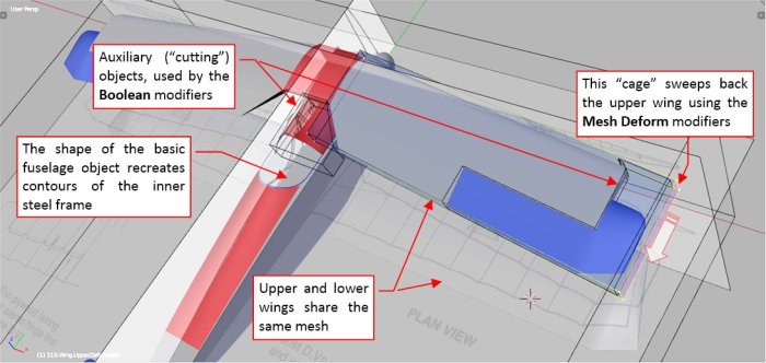
In the result, the simple deforming “box” of the Mesh Deform modifier completely controls the shape of the upper wing.
Of course, the tip of this upper wing has a simplified, “block” shape. Since I was requested to recreate the fuselage frame, I also skipped in this model the side fairings. (They were made of fabric stretched around wooden fittings, attached to the steel frame). The basic fuselage shape of this model corresponds to the shape of this frame – I even rounded the edges of this object using (in the Bevel modifier) the probable radius of the longeron tubes (10 mm). I only added the fuselage details that will enable me better matching the silhouette of the aircraft with the photos: the upper fittings, edge of the cockpit opening, and the engine cowling (without the cutout in the bottom). The rudder and elevator are simple planes, made 10mm thick using the Solidify modifiers.
For the first photo matching, I selected a side view (Figure 96‑5), because in this way I excluded the eventual errors caused by wrong widths or improper spanwise position of the wing struts. In general, matching such a photo is a “trail and error” process. I attached the reference photo to the camera and made it partially transparent, so that I could see my model through it. This camera points toward the auxiliary target object (Figure 96‑5):

I could pan/move the model over this photo by moving the camera target object. To change model orientation, I orbited the camera around the model, and adjusted its distance. There was also another variable: the intensity of the perspective distortion, controlled by the camera lens length parameter. While adjusting these parameters this in the left window, in the right window I could see the current camera view. To find the proper projection, first I found the camera and target locations that produced an acceptable approximation of the photo. Then I tried to fine-tune this result by altering the camera lens length.
In the ideal perspective projection, all straight lines remain straight. So they are straight in the Blender camera view. However, the photos made by the real camera lenses have additional, so-called “barrel distortion”. (Its extreme cases you can observe in the wide-angle, “fish eye” photos). I could not estimate and eventually compensate the barrel distortions of these old Fokker D.V photos. Thus, I had to fit my 3D model into several similar photos, hoping that each of them is distorted in a different way. I assumed that the model shape, which fits all these photos as close as possible, minimizes the influence of their individual distortions. (This is a simple rule of “multiple witnesses”). Figure 96‑6 shows another matched photo. This time it is a classic ¾ view:

In the result of this matching I made several adjustments in the model (Figure 96‑7):

Most of them were concentrated around the lower wing: I had to move it a few centimeters downward, and, together with the undercarriage, 10cm forward. The bottom part of the fuselage was also a few centimeters lower than on Ian Stair’s plans. It seems that the wing bay was shorter: 50cm, as well as the wing chord: 110cm instead of 115cm. This last difference is a surprise, because the original Fokker general blueprint (the blue paper in Figure 96‑2) explicitly specifies this length as “1150mm”. However, if the wheel diameter is right (71cm, according another blueprint), then this wing chord is about 110cm (+/- 1cm). Otherwise the wings do not fit the photos.
Note that I had some doubts about the oversized wing tips in Figure 96‑6, but for the time being I decided that this is an side-effect of the simplified (thicker) tips of my model.
Then I started fitting this model into the photos taken from more frontal directions. First, I mapped two photos of the same Fokker D.V wn 2721, named “Hamster” (Figure 96‑8):

As you can see, there was something wrong with the wing tips: while all the other elements matched the picture quite well, these tips extended far beyond the wings depicted on the photo.
To make sure, that this particular Fokker D.V wn 2721 was not a modified version, I used photo of another aircraft (Figure 96‑9):

However, when I decreased the wing span of the model (scaling down the wings along their spars), it matched the picture in this photo (Figure 96‑10):

Of course, I checked these shorter wings against all the previously mapped photos. (I even prepared an auxiliary add-in in Python, which enables me to switch with a single button click between subsequent photos and their projections). It seems that the true wing span of the Fokker D.V was 815cm, and its ribs were spaced at 37cm from each other.
At this moment we can conclude, that this aircraft had a different length/span ratio than specified in its general description. But which of these two dimensions is true: the span or the length?
If the Fokker D.V wing span was 815cm, then the wheel diameter was 71cm (as in the blueprints of the landing gear), the diameter of the engine cowling was 107 (+/- 1) cm, and the length of the aircraft was 605cm (as in the blueprints):

Otherwise, if the span of the Fokker D.V wings was 875cm, then proportionally the wheel diameter was 77cm (instead of 71cm from the blueprints), the fuselage length was 650cm, and the diameter of the engine cowling was 115cm.
The diameter of the Fokker D.V rotary engine (Gnome/Oberursel) was 101cm. Thus, the more probable engine cowling diameter is 107cm, and it implies that the fuselage length was indeed 605cm, as specified in the Fokker blueprints.
If the wing span of this aircraft would be 875cm then the man in Figure 96‑9 would be 193cm high. This is less possible, especially when you do similar estimation for the other photos of the Fokker D.Vs and their crew. All these men would be over 180cm! Even today it is hardly possible. What’s more, 100 years ago men were somewhat shorter!
You can note, that two of the four dimensions given in the Fokker D.V overall blueprint occurred to be false. What’s more, this picture differs in many aspects from the real aircraft (Figure 96‑12):

Why the Fokker “general” blueprint specifies wing span as 875cm? Maybe it was originally hand-written as “8150”, and somebody read “1” as “7”? I also cannot explain, why it states tat the wing chord was “1150” instead of “1100”. Maybe because “1150” was the chord length of the earlier Fokker biplane of similar size – the D.II? The D.V was similar to D.II in many aspects. At least this shorter chord length is confirmed in a book from 1918:

As you can see, the span of the D.II and D.V in this table are identical: 8750. Somebody in the Fokker office could just copy this figure from one line to another…
I have no photo that would reveal the proportions of the elevator. However, C. West suggested that the Fokker D.V could use the same rudder and elevator as in the D.III and D.IV (Figure 96‑14):
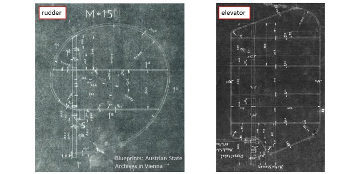
I checked that the D.III rudder shape perfectly matches the photos, so I shaped the elevator according the D.III / D.IV blueprint. Figure 96‑15 shows the result, compared to the initial scale plans:

I also tried to recreate the contours of Fokker D.V ribs from manufacturer’s photos. It seems that the D.V airfoil is similar, but slightly thicker than in the D.II (Figure 96‑16):

Finally, when the overall geometry was verified, I could use the matched photos as the detailed references in recreating the fuselage frame (Figure 96‑17):

When the reference photo is properly matched, you can use it as easily as the scale plan. You just have to get used to building the 3D model in a non-orthogonal view.
Of course, then I also used the other photos to check the geometry of this structure (Figure 96‑18):

Using these pictures I built the model of its fuselage frame (the steel part, made from welded tubes). Figure 96‑19 shows the final result: a recreated geometry of the nearly forgotten WWI fighter:

As I previously mentioned, this model is built of simplified components – it results, for example, in the “blocky” tips of the upper wing. It also lacks the engine, cables, cockpit, etc. However, it forms a solid base for a more detailed model, or decent scale plans.
Here is its source *.blend file.
The photo-matching method allowed me to make a small contribution to updating the historical data about this aircraft. The most surprising “discovery” was that the real Fokker D.V wing span – shorter by 0.6m than the span published in all the books (8.15m, instead of 8.75m). I call such a mistake “an Aristotle’s effect”. This name comes from following story:
Many centuries ago, in the middle ages, all what was left after the mighty Roman Empire was a few ruins and some ancient scriptures, preserved in the monasteries. The monks copied them, allowing the others to learn about the half-forgotten ideas of Greek philosophers. One of the most popular books was Aristotle’s “Natural History”, which described the world of animals and plants. One of its copyists made a small mistake and altered the sentence “flies have six legs” into “flies have eight legs”. Unfortunately, the copy with this sentence was used as the base for most of the other copies of this book. In the effect, for centuries the other monks repeated the statement that “files have eight legs”. None tried to count the legs of the creature that walked on the edge of his desk!
If you think that such a thing can happen only in the “dark middle ages”, then look at this fragment of the Fokker D.V geometrical data (it is copied from one of the publications about his aircraft):

The Fokker D.V wing area is specified here as “15.5m2”. You can find this area in many other sources. However, using the span and chord length, it is quite easy to estimate the wing area for such a WWI biplane, where both wings had the same span and a fixed chord. Let’s do it for the figures specified in this picture, calculating the area of equivalent “rectangular” wings:
“Rectangular” wing area = 2* (8.75m*1.16m) = 20.3 m2
The sweepback of the upper wing has no influence on this result. After adjusting this area for the non-rectangular wing tips (-0.85m2), and the cutout around the cockpit (-0.58 m2) we would get the wing area of about 18.9m2! Even if we assume that the Fokker in those early days did not include the fuselage between the wings into the wing area (0.87 m2), the result will be 18 m2.
This quick calculation shows, that somebody who published dimensions shown in Figure 96‑20 did not check these figures. (You can make such a calculation manually, on a scrap of paper). This is a pure “Aristotle’s effect”!
However, if we consider the smaller dimensions of the wings obtained from my photo matching, the result will be much closer to the published area:
“Rectangular” wing area = 2* (8.15m*1.10m) = 17.93 m2
I estimate the real wing area (adjusted for the wing tips shape: -0.82m2 and the cutout: -0.50 m2) as 16.6m2. (These adjustments are slightly smaller than in the previous case because of the shorter wing chord and narrower rib spacing). If we exclude from this result the area of the fuselage between the bottom wings (0.83m2) we will get 15.8m2. It differs from the “15.5 m2” area just by 2%.

I like your math! Caught you over at M-M.
LikeLike
Fascinating stuff! Thanks for sharing.
LikeLike
I found the same with several Nieuports – the Nieuport 12 has the same length fuselage as the 10 (which I discovered having measured the Ottawa Nieuport 12 AND the Old Rhinebeck 10/83), but all the references claimed it was longer, however I found that the official rigging drawing used the length tail down, with prop blade jutting out, rather than tail up from hub to rudder – and then applied the dimension incorrectly to the drawing. For years, the later Nieuport scouts (24/24bis/27) have been claimed to be longer than the 17/21/23, however the official drawings show them to be within 5mm of the German drawings of a captured Nieuport 17 when measured from firewall to rudder post – well within the variation one would expect from high volume production. I have found that there are many ways someone can measure something as simple as length – with or without the prop, up or down, and with or without the rudder! Span is the same deal – they could add or omit the overhang from the ailerons, and then there is the possibility that the design was changed from when the drawings were completed, and they were never updated – which I have also encountered.
LikeLike
Two minor points:
1. Image 96-15 says the crosses on the upper wing were painted parallel to the leading / trailing edges. In the drawing the crosses are not parallel. Yes, you have already demonstrated the drawings are incorrect but do you have a photo to show the correct upper wing crosses?
2. Figure 96-19 is incorrectly labelled as 96-9 in the text below the photo.
Great job. I love the analysis.
LikeLike
I am happy that you have found this post interesting.
About p.1: yes, the photos of this Fokker show that the crosses were painted perpendicular to the leading/trailing edges. I cannot demonstrate all the pictures that I obtained from C. West, but you can see this, for example, in this photo: https://i.pinimg.com/originals/24/7c/c0/247cc0dd81dbd67744f57b51cbeba46f.jpg
This is nothing new: in Google images I can see many Fokker D. V models with crosses painted in this way (so the modelers already knew this detail).
Thank you for pointing p. 2!
LikeLike