While working on the cowling details, I discovered that the SBD-5 from the Commemorative Air Force (“white 5”) uses a non-original Hamilton Standard propeller. It has larger hub and a pair of bolts in the middle of the hub barrel edges. (As I wrote in this post, the original Hamilton Standard hubs used in the SBDs were smaller, thus they had a single bolt in the middle of each barrel edge). What’s more, I also noticed that the centerline of my model does not precisely pass through the tip of the propeller dome visible in this photo. When I corrected this mistake, I also noticed that the edges of certain cowling panels in my model are minimally below their counterparts on the photo. I examined this difference and decided that I should fix it by rotating the camera of this projection around the fuselage centerline. It was really a “cosmetic” adjustment — the rotation angle was about 0.7⁰. However, suddenly everything in this model matched better the reference photo — except the horizontal tailplane (Figure 58‑1):

When I previously matched my model to this photo (see Figure 42-9 in this post), I aligned it along its horizontal stabilizer. (I assumed that it is not deformed by any significant load). It seems that I was wrong: the Dauntless on this picture is taking off (its wing flaps are retracted). What’s more, its elevator is slightly rotated upward, what means that this airplane has already gained enough speed and currently the pilot is lifting its nose to leave the ground. Thus there is an aerodynamic force which bends the tailplane downward, while the lift force tries to bend the wingtips upward (Figure 58‑2):

I think that I would obtain a perfect match between the fuselages of my model and in the photo by placing the viewpoint of this projection between its previous and the current location. (In its previous location it matched the deformed tailplane, while in the current one — it matches the deformed wing).
However, both of these tailplane and wing deformations are small. Thus aligning the wing of my model to the wing in this photo delivers me much more useful information, than a “geometrically pure” match somewhere between these two points. The influence of viewport rotation of 0.7⁰/2 = 0.35⁰ on the fuselage can be neglected, and now the only part of my model that does not fit the photo is the tailplane. It’s OK, because in this projection I cannot see any special details on this element. On the other hand, now I can use this high-resolution photo to check various details on the bottom side of the wing.
Currently we are close to the end of the modeling stage of this project. All the elements of this model that I am going to ‘unwrap’ for the image textures are already in place. Now I will use this high-resolution reference photo to re-examine the model shape and fix all the remaining differences. I started from the empennage (Figure 58‑3):

I fixed it working directly on this picture (I restricted the movement of the mesh vertices to the global YZ planes).
Then I shifted forward, fixing the dorsal fin (Figure 58‑4):

There still was a difference in the tail bottom contour. This time I had to alternate the lower part of the tailplane bulkheads (Figure 58‑5):

I did it by scaling these parts of the bulkheads downward. The most difficult part of this operation was the preservation of the straight lengthwise (“longeron”) edges in the rear part of the tail.
Of course, I also used other photos for this check. In Figure 58‑6 you can see matching the wing against a “semi-vertical” shot of a Dauntless in a steep bank (most probably in a tight turn):

I can see here a difference in the wingtip shape. However, I already verified it against other photos, several months ago (see Figure 31-8 in this post). What’s more, I discovered that when I slightly rotate the wing tip around the wing span axis, it perfectly fits the photo (Figure 58‑6b). Thus I again started to think about the forces — this time acting on these wings in such a turn. The lift force has to counter the centrifugal force here. For such a steep bank it can be several times greater than the weight of the aircraft. Thus the wing in this photo is under extremely heavy load, and it wing tips can be twisted as severely, as those in Figure 58‑6b). Ultimately I assumed that this is an effect of dynamic deformation, and I should not modify the wingtip. (The photos of this wing in static conditions do not confirm this shape).
However, in Figure 58‑6c) you can see another difference that has haunted me for a long time: the gap between the wing flaps and the aileron. On the various photos, both static and in-flight, it seems that the trailing edge of the wing flap was a little bit shorter than in my model.
First I checked if in this photo the flap is not shifted nor rotated (Figure 58‑7):
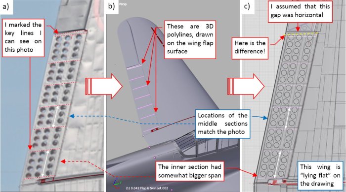
I placed auxiliary lines on the flap surface of my model. They go along the last row of holes in each of the 6 segments of this flap (Figure 58‑7a, b). These lines reveal the “natural” direction of the flap ribs. At the outer end of this flap I put a polyline, which upper edge matches the flap upper. (I wanted to check if this edge is parallel do the flap ribs).
Then I put the wing and these auxiliary lines flat on my reference drawings (i.e. I set the wing dihedral and incidence angles to 0). You can the result in Figure 58‑7c). It seems that the middle sections match my reference drawings (and my model). However, the most inner section (containing the four rows of three holes in each row) should be slightly wider, while the most outer section was shorter (although it contains the same number of holes!). This result was a little surprise, because when I drew these scale plans, I assumed that the spacing between the flap holes was constant. (It would be easier to machine such a perforation). Now it seems that this distance varies in different segments of this flap! Finally, the polygon on the outer end of the flap clearly indicates that its outer edge is oblique (see Figure 58‑7c).
Of course, I verified these findings in other reference materials (Figure 58‑8):

The close-up photos of various aircraft confirmed that the outer edge of the upper flap was slightly oblique (Figure 58‑8a). I can also see that the distances between the rows of holes in the last flap segment were shorter than in the segments in the middle. (It implies that the spacing between these rows in the most inner segment could be also a little bit wider). What’s more, I could see these differences in one of the original Douglas drawings (Figure 58‑8b). However, I neglected them before, because this is not a regular, orthogonal view. (Such a drawings can be often deformed in various ways).
Thus I modified the aileron and the flap according these findings (Figure 58‑9a). When I attached wing to the centerplane (i.e. when I set its incidence and dihedral angles) I discovered that the corresponding aileron and flap edges became vertical in the rear view (Figure 58‑9b):

An additional headache was the outer edge of the bottom flap, which was parallel to the last rib (Figure 58‑9c). Ultimately I decided that most probably the outer corners of the upper and lower flaps overlaps as in Figure 58‑9b).
Of course, I reviewed the whole model and made much more minor adjustments. I will not bother you describing them all. Fortunately, most of them did not require as much work as this small gap!
Figure 58‑10 shows the resulting SBD-5 model:

In this source *.blend file you can evaluate yourself the current version, described in this post.
In the next post I will start the “painting” stage of this project. I begins with mapping of the texture coordinates (UV) onto the model surfaces (so-called UV-unwrapping).

One thought on “Final Adjustments of the Model Shape”