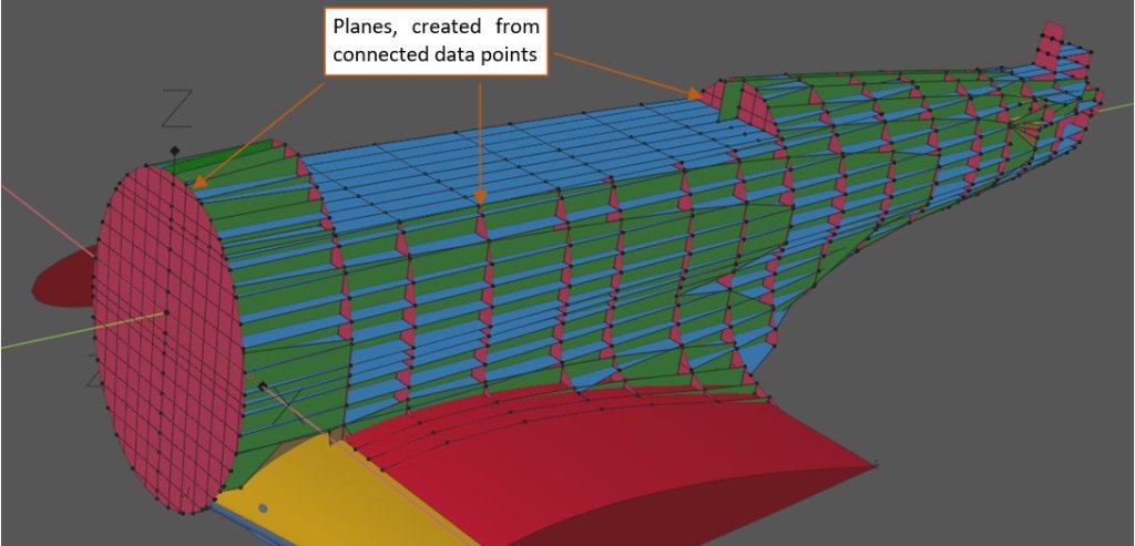
In the previous post I used ordinals from the newly found fuselage geometry diagram for creating a set of the 3D reference planes:

In this post I will span a smooth subdivision surface between these points. I think that such an interpolation will provide a more accurate reference than the longerons (stiffeners), which I previously shaped in this post (see there Figure 112-07).
I compared my previous approximation of the fuselage shape, based on the partial data from the NASM microfilm, with these ordinates. In general, it seems that it was quite accurate:

The wing fillet fits well these ordinates – its shape requires just some minor adjustments. On the other hand, I can see that the radius of the upper parts of the tail bulkheads was somewhat smaller. At least I was right, assuming that this radius was constant along the rear gun doors. In this way these doors could be formed as a part of the cylindrical surface, which simplified their production.
Ordinates from this SDASM blueprint confirmed many of other assumptions that I made basing on the partial NASM blueprints (see my first two posts on the fuselage geometry):

Note the flattened cross-section of the wing root fillet. This diagram confirms my hypothesis about this shape, based on the shape of its trailing edge in the top view (see this post). It also confirms another assumption: that in the rear view all the fuselage stiffeners (I called them “longerons”) run along straight lines, spanning radially from the fuselage center. In the tail area, these lines are equally spaced: 15° from each other. In the mid-fuselage some of them are bent upward.
When I looked at the forward part of the fuselage described by the Douglas geometry diagram, I realized that there is something wrong with the upper contours of frames 1 and 2:

While most of the frame 1 data points perfectly fitted the firewall assembly drawing, they missed the “bulged” covers around the fuselage guns. Fortunately, I was able to recreate this cowling using dimensions from the windscreen and firewall assembly drawings.
I think that this diagram was based on the original Northrop XBT-2 prototype drawings. As you can see below, the upper cowling between frame 1 and frame 2 looks like in the geometry diagram:

XBT-2 was equipped with a single forward-firing gun, mounted on the right side, in the front of the pilot. Thus, left contours of its frame 1 and frame 2 could match the elliptic shape, depicted in this diagram. I suppose that the geometry of all other XBT-2 fuselage frames (3 … 17) match their counterparts in the serial SBDs.
Illustration below shows the smooth surfaces, spanned over the reference polygons. In this case, I corrected the shape of the wing fillet surfaces (blue and red), extending them up to frame 13. Then I added new surface (gray) which covers the main portions of the fuselage. Behind the cockpit, I fitted its shape to the cylinder. Upper parts of this cylinder cross sections fit the corresponding ordinal points of the fuselage frames:

To make sure that this “skin” passes through the original geometry, I placed it little below the ordinal points. In the effect, the vertices of the reference polygons minimally protrude from this surface – by about 0.01”. This is well within the range of eventual errors in locations of these ordinal points, and below the thickness of the real fuselage skin (0.03”). In this way I was able to visually check if the modeled surface fits all ordinal points.
On the other hand, the geometry of the WW2 aircraft was always given “as for the skeleton”, i.e. did not take into account the skin thickness.
When I compared the resulted shape with the fuselage assembly blueprint, I saw that its upper contour precisely follows the ordinates. There were some minor differences along the bottom contour plotted on this drawing:

These minor differences are OK, since these lines on such an assembly drawing are of least importance. In this blueprint, the key information are the referenced part numbers.
However, some months ago, when I did not have these explicit ordinates, I concluded that the upper fuselage contour was 0.3” higher than on this blueprint (see this post, figures 113-7 to 113-9). It looks like that on this high-resolution photo, which I matched with my model:

Because the explicit dimensions did not confirm these findings, I verified this hypothesis using matched photos of another restored SBD-5:

In both aircraft we can see identical difference in the dorsal fillet shape, but the fuselage, shaped according to the ordinals, perfectly fits the second picture. There is no visual difference, especially as significant as 0.3”. Thus – this higher upper contour is an individual feature of the restored SBD-5 from the first photo. Most probably they inaccurately rebuilt its tail section.
When you are looking into something for too long (as I did in the case of this fuselage) you can sometimes “find” a non-existing feature! In such a case, the explicit dimensions, as these ordinals, are invaluable.
On the other hand, I suppose that these photos depict the true shape of the dorsal fillet. (Unfortunately, its ordinals were provided in a separate blueprint, which is still missing.)
One thought on “Original SBD Dauntless Blueprints: Fuselage Geometry (4)”