Drawing the vertical views (from the top and bottom) of the SBD Dauntless was more difficult than the side view, because there were no “vertical” photos which you can use to verify and enhance the available plans.
Anyway, I started using everything I could, for example some photos from the restoration done by the Pacific Aviation Museum (Figure 8‑1):

The photo on the picture above has a strong barrel distortion. We cannot effectively “revert” it as we did for the side view. Why? Because the photo of the side view all contours of the aircraft lie on a single plane (the symmetry plane). This one contains are at least three important planes: the edges of the cockpit, the center of the fuselage (along its maximum width) and the wing contour. Each of them is located at a different distance from the camera, and each requires different distortion (fixing one of them you would spoil the others).
Nevertheless, taking all of this into account, this high-resolution photo is still useful to determine the rivets pattern of the center wing section, as well as the width of the cockpit frame. The edge of the Dauntless cockpit is formed by an important longeron: it determines the fuselage shape in this area. To precisely estimate the width of the cockpit canopies I draw auxiliary contours of their cross sections (you can see them on the picture above as the blue lines). Positions of the bulkheads are copied from the side view. On this top view I roughly approximated positons of the longerons below the cockpit edge. This is just a “workshop drawing”, not a regular scale plan: I will form the fuselage following its contour on the side view and a few key cross sections which I will draw later. Because of the barrel distortion of the reference photo I was not able to check the contour of the fuselage in the top view. This is the only element I had to redraw without any verification from the Douglas general arrangement drawing.
In next step I used dimensions from the Douglas diagram to draw the trapezes of the outer wing panels and horizontal tailplane (Figure 8‑2):

Picture above shows all the lines which you can deduce from the general dimensions provided by the manufacturer. We can further enrich it using the information from the stations diagram (Figure 8‑3):

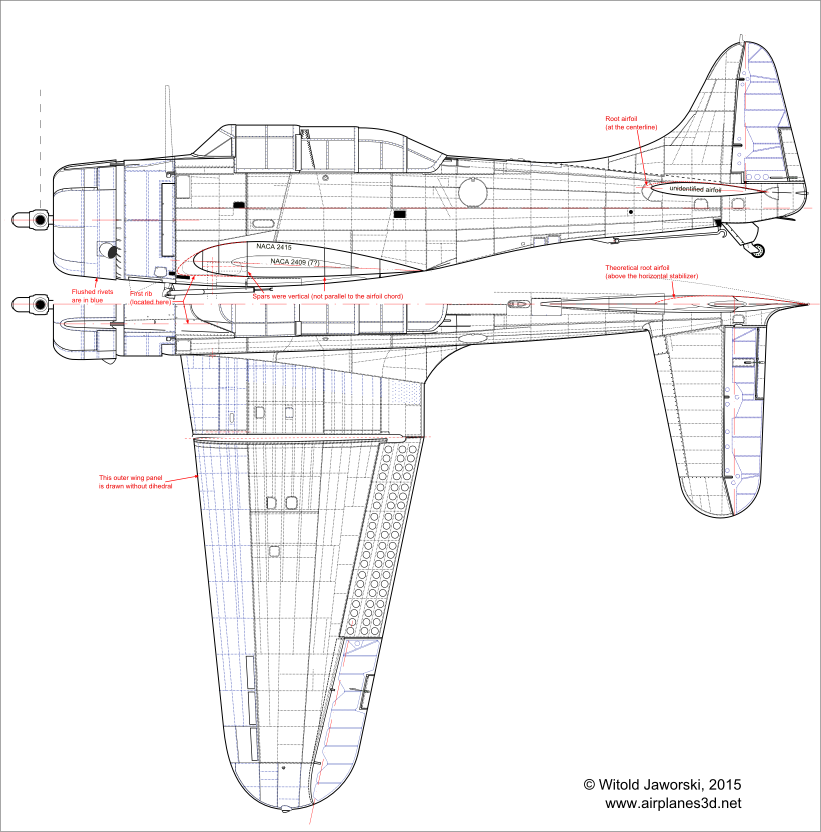
The station diagram provides precise position of all wing ribs. Most of them are just a row of rivets, but along some of them you can find the panel seams.
All right, but this wing drawing is still missing its “vertical” elements: rivet and panel seams along the spars and stringers. How to determine their locations?
I had to review all the collected photos. Ultimately I chose one of the pictures from the web page of Chino Planes of Fame Air Museum (Figure 8‑4):

I rotated this photo, aligning the wings of this airplane to the vertical guides. As you can see, it is made with a telescopic camera, so that it is very close to a perfectly orthographic projection. (The guides of the tailplane are not ideally parallel to corresponding guides on the wings, but this difference is minimal). The left wing is depicted at a relatively high angle, so you can see clearly the rivet seams along the spars and stringers. I decided that I can use this picture to map these lines onto my drawing.
I flipped this image from right to left, and stretched it, fitting its wing into the basic trapeze (Figure 8‑5):

It allowed me to recreate the wingtip curve. In such a highly-deformed image the rib lines are bent. They match their “true” positions only on the wing edges. However, we can easily map from this image the spar and stringer lines. All of them continue from the center wing section. Combined with the ribs these lines form a kind of the “reference grid”, which cells allowed me to draw all the remaining details: the circular holes in the flaps, fixed slats openings, etc.
I used similar method to map the tip of the horizontal tailplane as well as its two spars. In the effect I obtained a detailed top view of the SBD Dauntless.
In the next post I will publish the bottom view (I am just working on the last details).

Witold,
I’ve been able to use these techniques to good effect on my F-100 project. I found three pictures of an F-100F in a highly banked attitude, taken with a really long lens, and have been able to regress all three to near-identical plan view images that fit neatly into my wing trapezoid. By this means I’ve been able to deduce dimensions and define panel lines that don’t appear elsewhere in my documentation. I was able to use the perspective correction tool in Paint Shop Pro on both wings simultaneously because the F-100 wing is exceedingly simple: no dihedral, no twist, no wing root incidence, no section camber, and no thickness taper. Just a symmetrical 7% NACA thickness form from root to tip at a 45 degree c/4 sweep. The whole wing, left and right, lies in a single water plane. It turns out using the perspective correction tool gives a slightly different and more accurate result that just stretching and shearing the image to the trapezoid.
This geometric simplicity of the F-100 is actually one of the chief reasons I chose this subject as my first project. In many ways it is a trivially simple airplane. The La-5, let alone the P-40 or SBD, is a beast of intricacy by comparison.
LikeLike
Great! I am happy that this method also works in your case. You are right, the image adjustment by simple stretching is not as good as the perspective correction. (I used it basing on the assumption that the perspective deformation of the wing can be neglected on the photo presented in the post).
BTW: indeed, the early jets had relatively simple and clean shapes (the MiG-15, with its circular fuselage cross section is an extreme). However, I would rate the F-100 fuselage in the medium of the difficulty scale (it has rather complex cross-section, and there may be problems with its verification).
LikeLike
Yeah, the F-100 cross sections can be tricky, but they transition smoothly and predictable as conics from nose to tail. The fuselage maximum half breadth also seems to lie in a water plane more or less coincident with the wing reference plane. Fortunately, I have access to a F-100D about a mile from where I work. I’ve already taken about 1,000 photos of it from all angles. I’m working out techniques to develop loft lines from the photos.
LikeLike