Here is a printable (PDF) version of this tutorial. It contains much better images than the automatically processed copies, which you can see in this post.
In my previous post I “fitted” my model of the P-40B into modern photo of a restored aircraft. (Precise speaking, it was a photo of the P-40C, but there were no external differences between these two versions). In general, I used Blender camera object to “pose” the 3D model so in the camera frame it looks just like the aircraft depicted in the photo. One of the key information that I used for this “fitting” was the lens focal length used for making the reference photo. (Modern cameras save key technical parameters in the resulting image file). I could just read this length from the photo properties, write it to the corresponding Blender camera Focal Length property, and focus on determining the remaining unknowns: camera location and direction.
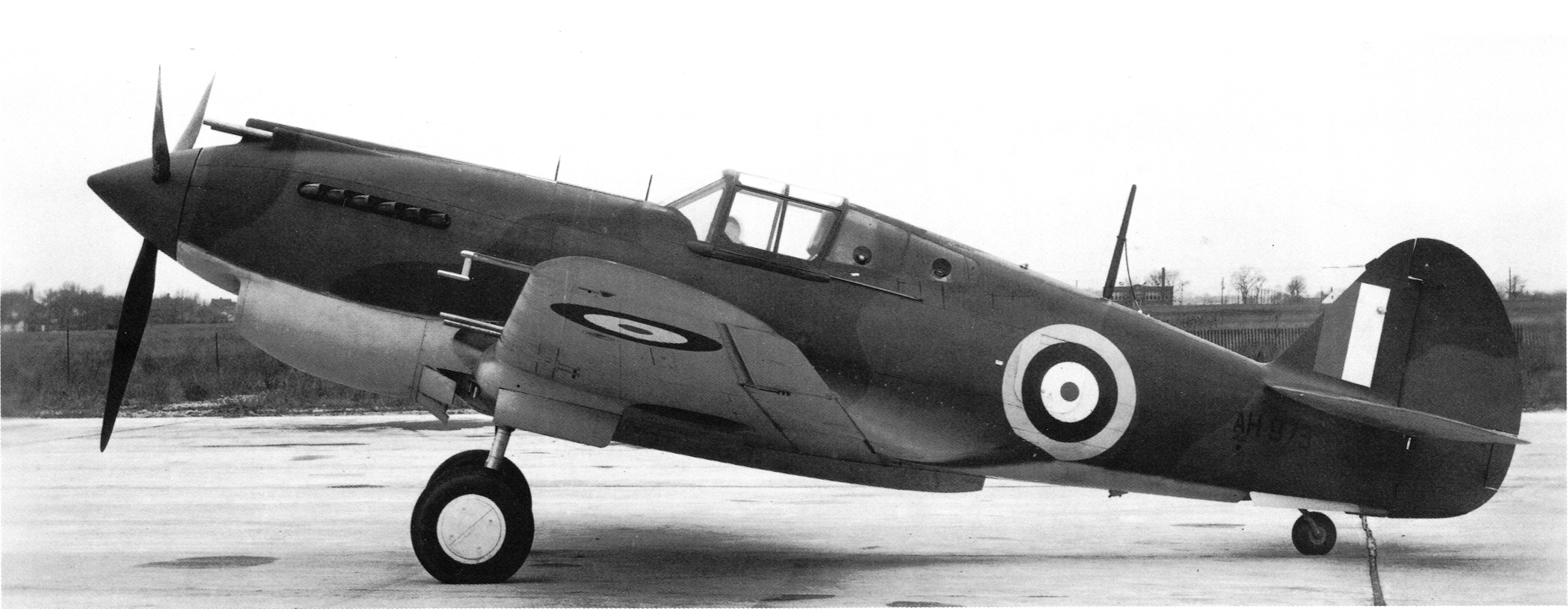
However, how to use the historical “analog” pictures for such a match? (For example – this original Curtiss photo of the Tomahawk IA from November 1940:)

For such a photo the camera focal length is not known. Worse, these old camera lenses were also prone to so-called “barrel distortion”.
Let’s discuss first the basic geometrical deformations which you can encounter in photos. The most obvious is the shape deformation created by the perspective projection. I will present it on the example of a simple “house” object. (A real, complex shape of an aircraft would obscure the key issues that I want to demonstrate below):

In perspective projection all straight lines remain straight. However, their angles can change, thus lines that are parallel or perpendicular in the 3D space, are no more parallel or perpendicular when projected onto the plane of the perspective camera frame.
Note, that there is a special case for the planes that are parallel to the camera frame:

Perspective projection of a shape that lies on a plane parallel to the camera frame also preserves the angles. This mean that the walls marked in Figure 104‑3 retained their original shape (in particular – the right angles at their corners). However, note that the relative size of these walls still depends on their distance from the camera: in the 3D space edges “A” and “B” from Figure 104‑3 have identical length. However, in this projection edge “A” seems to be longer, because it is closer to the viewpoint (i.e. to the camera).
Since Blender cameras create pure perspective views, this kind of projection is not an obstacle in using photos as precise reference. (I showed this in Figure 103‑23 from the previous post).
The aircraft profile (its outline on the symmetry plane) from a side-view photo, taken from a direction perpendicular to aircraft symmetry plane, should match the corresponding side-view profile in the orthographic side view. (If the photo is not distorted – see the discussion below). Of course, in the real world you will never encounter a photo made from such an “ideal” direction. They will always differ by (at least) few degrees.
Unfortunately, in the real-world cameras the perspective projection is combined with a side effect, called distortion. Below you can see an example of the most common negative (also called “barrel”) distortion:

If I removed from this picture the auxiliary grid and cropped the rounded edges, the image distortion would be hard to notice. You can only detect its presence checking the long lines that should be straight in the pure perspective projection. If they are curved like those in the picture above, then the image is distorted. A strong barrel distortion can be more visible when the photo was made with very short lens length (when its starts resembling a “fisheye” projection).
The long, telephoto lens can produce positive (“pincushion”) distortion:

As in the case of the barrel distortion, you can detect this image deformation by checking shapes of the long, originally straight lines (or edges).
Finally, you can also encounter a combination of the negative and positive distortion:

In the picture above the negative (barrel) distortion dominates in the center, while the positive (pincushion) distortion winds the image corners outside. In this case the overall image deformation is less significant, because these two distortions partially compensate each other. The lines that are straight in the 3D space are bent here along complex curves, which shape resembles a flatten mustache. (Thus, this kind of distortion is often called “mustache distortion”).
Practical tip: the center of the photo is always least distorted. You can expect the largest differences close to its edges. (Assuming that the image is not a cropped fragment of a larger original).
Sometimes you can detect barrel distortion using certain elements of the environment depicted around the aircraft. For example, a few years ago I used with some success the airstrip slabs edges as the equivalent of the “long straight lines” visible in the figure above. When you find such an “indicator” in a photo, you can compensate the distortion in this image (for example in GIMP, using “Lens Distortion” filter – see this post for details).
You can also find similar concrete slabs in the Curtiss photo presented in the beginning of this post, so I loaded it into Inkscape and used auxiliary guide lines to check if they are curved. (You can download the original picture from here):

As you can see in the picture above, the slab edges seem to be straight, so there is no evidence of any distortion in this image.
Additionally, I have found a cropped version of this photo in Francis Dean’s “Curtiss Fighter Aircraft” book (published in 2007). The illustration in this book seems to have a higher resolution than the image shown in Figure 104‑1. I decided to use it for checking the proportions of this photo. (I am always afraid that a web/book designer could stretch a little such a picture, fitting it into desired space on the web/book page. Such a deformation makes it unusable for the photo matching). Thus I scanned this illustration and placed it (in Inkscape) under the full-size image. Then I looked for any difference between these two pictures. Fortunately, there were none.
Let’s fit our 3D model into this photo. For this purpose use the scanned image (outlined in Figure 104‑7 with dashed line), because of its higher resolution (4493x1744px). Here is the link to this picture.
Open in Blender the resulting file from the previous part of this tutorial (the previous post).
Now we need to add to this scene another camera and camera target object. You could set them up as I described in the previous post (see from Figure 103‑4 to Figure 103‑9). However, you can also copy (duplicate) the DUX-1 camera and DUX-1.Target objects (i.e. the objects set up in the previous post):

Just select both: camera and target, and from 3D View Object menu call Duplicate Objects command ([Shift]–[D]). (Note: invoke this command when a 3D View window is the active window. Otherwise the shortcut will not work). It creates duplicates of both objects, named as shown in the figure above. Now change the new camera name to CTS-1 (or any other name that suits you), and its target object to CTS-1.Target (Figure 104‑9a):

Finally, to not confuse the target objects, create a new, invisible collection named (for example) “0C. References” and moved there the DUX-1 camera and its target (as in Figure 104‑9b)
Then update the background image in this new CTS-1 camera:

Decrease also the focal length of this camera to 80. (Type this value into Focal Length field in Lens panel, as shown in previous post, Figure 103‑4). We do not know the precise focal length of this camera, this is just an initial approximation.
In the next step update the camera aspect ratio to 4493×1774. (Enter these new background image dimensions in the Properties window, Output section, Dimensions panel, as shown in previous post, Figure 103‑13)
Finally set CTS-1 as the active camera (calling View:Cameras:Set Active Object as Camera). Below you can see how its initial frame looks like:

The model in this frame looks so small because you have reduced the lens length from 525mm to 80mm. Now you have to shift the camera closer to its target (as you did in previous post, instruction above Figure 103‑17, or at Figure 103‑7). Then rotate the camera and its target around the model (precisely: around the 3D Cursor, located in the model center – as in previous post, Figure 103‑19).
After some further adjustments (rotating and panning the model in the camera frame – these transformations are also described in the previous post) you can get a result similar to following frame:
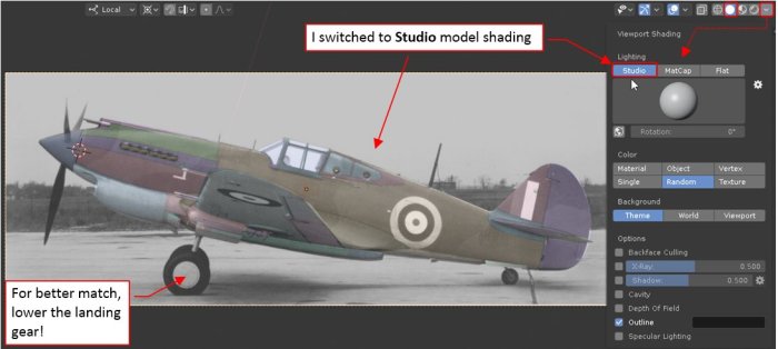
I suggest switching the viewport shading mode from Flat (set in the previous post) to Studio, because for this kind of matching such a more natural shading looks better (as in Figure 104‑12). In this model you can also lower the landing gear. I modeled its main wheels and their oleo struts using the P-40E blueprints (although I did not used explicit dimensions for their exact location in relation to the wing). I think that when coupled with the wing, they can be useful for better photo matching.
This model has many “moveable” parts, so I prepared a special Blender add-on named “Handle Panel”. This plugin provides user interface controls for easy “posing” a complex 3D model (see section 4 in this article). Download and install in Blender the Handle Panel add-on. (If you do not know how to install an add-on in Blender: see here). Then enable this plugin (in the Edit:Preferences window – see Figure 104‑13a), and click the Show/Refresh button in its panel (you will find it in the Properties Window, Scene tab, as in Figure 104‑13b):

The Show/Refresh button fills the Scene tab with small control panels for the “moveable” model elements (like the landing gear, control surfaces, flaps, canopy hood, etc.). To lower the landing gear, set the 00. L. Gear Retraction slider to 0% :

Then use the 10. L. Gear Deflection slider to adjust the oleo strut deflection, so that the main wheels in this model will match their counterparts in the photo. (Do not pay attention to the tail wheel. It seems to be totally wrong. It looks that I used there the smaller wheel, like the one used in the P-40cu, while the longer fork and oleo strut came from the P-40D. I wrongly assumed that this assembly was identical in all of the P-40 versions).
You can also use the 99: Propeller handle to rotate the spinner, matching the blade positions in the photo
Lowered landing gear (especially the left oleo strut, which obscures the right one) will help you to determine the precise camera location in the horizontal plane. However, now the wing leading edge does not match the photo, and the right wheel seem to be lower than in the reference image:

Such differences can indicate that you should adjust the camera lens length. However, when you decrease the Lens: Focal Length value even by a few percent (let’s say from 80mm to 77mm) – the model visible in the frame becomes smaller:

Now you have to compensate this effect by closing the camera (along its local Z axis) to the model. The necessity of such compensations makes lens length adjustments quite cumbersome. (After every focal length adjustment, you have to fit the model to the photo anew).
Addressing this problem, I created a special Blender add-on. It works for the cameras that are associated with a background image and a target object (via an active Track To constraint) – just like our current camera. When you alter the focus length of such a camera, this plugin automatically adjusts its distance from the target object:

The distance is adjusted proportionally to the change in the camera lens length (f), so the relative size of the target object in the camera frame remains constant. This means that all points from the neutral plane, which is parallel to the camera frame and contains the target object center, are fixed.
In the side views the aircraft profile lies on the symmetry plane, which is nearly parallel to the camera frame. Thus, if you also place the camera target in this plane, you will be able to alter the focal length while the fuselage size will remain fitted to the photo:

In this case, the target object occurs inside the cockpit. It would be quite difficult to select such an obscured object in this 3D View. Fortunately, you can also select it (as well as the camera) in the Outliner window, as shown in Figure 104‑18.
Now download this add-on file, unpack it, and install in your Blender. It is named Reference Cameras. As in the previous case, you can find it among the User plugins:

When you enable this plugin, it adds Cameras tab to the 3D View side panel (Figure 104‑19). In this tab I placed (just for the convenience) the Current (camera) panel with the lens length control. It also contains a panel named Ref Cameras, which we will discuss later in this post.
Once you enabled Reference Cameras add-on and placed the target object on the plane you want to be “insensitive” to the changes of the camera focal length, you can start experimenting with the lens length adjustments:

The best way to learn how the lens length affects your camera view is to change its value smoothly, with mouse. You can do it by dragging your mouse over the Current:Lens field, simultaneously keeping the [Alt] key down. (You can also use this trick in the Camera properties, Lens panel, altering the Focal Length field). If you want to increase precision of these changes – press also [Shift] key, while dragging your mouse.
If you notice that the camera view “blinks” after every change of the camera focal length, open and then minimize the Blender Preferences window (Edit: Preferences). This simple step eliminates “blinking” of this view. (I cannot explain this “blinking” effect, but I noticed that this add-on works smoothly when you have opened more than one Blender window – at least in the current Blender version: 2.80).
You will quickly discover that when you decrease the lens length, you are not only enlarging the size of the closer elements (like the left wheel or the wing tip), but also rotate this model a little. (Because this camera is not ideally perpendicular to the model symmetry plane). To see the difference, compare Figure 104‑15 (f = 80mm) with Figure 104‑20 (f = 52mm). To compensate this effect, you have to slightly rotate the target and camera around this model, in the opposite direction.
Adjusting the lens length, you are able to control proportions of the wing “trapeze” (relative chords at its root and tip). However, this photo was a difficult piece for a precise match. I could not find a projection in which both: the wing and the wheels match the reference photo. Ultimately I decided to focus on fitting the only “confirmed” (dimensioned) element of this model: the wing. Below you can see my best result, obtained for camera lens length = 67.8mm:

As you can see, I was not able to fit my model to this picture as precisely as to the modern photo from the previous post. There are several “doubtful areas”, even within the wing:
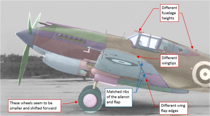
In the case of the different location of the landing gear wheels – it may happen that in this model I set their struts at wrong angle. Their diameter also needs re-checking. However, I cannot explain the difference at the wingtip: I fitted the chordwise edges of the aileron and flap match the photo. so the spanwise location of these elements match the photo. In spite of this, the wingtip on the picture is higher than in my model. Similar vertical variation also occurs along the upper edge of the fuselage. These differences did not appear between this model and the matched modern photo, which I presented in the previous post. Was this archival film distorted in other way? (for example – mechanically, in printing).
What to do in such a situation? You can (simultaneously):
- Re-check the “confirmed” dimensions of your model (you could make somewhere a mistake). In this case I should re-check the wings, and look for a new documentation, with at least some key dimensions of the fuselage;
- Match the model with more similar photos. In this way you will check which differences occur in more than one image (these cases reveal the real areas which you should fix);
For this tutorial, follow the second suggestion and match this model with other photos. For example, try this telephoto picture of a different P-40B (note the long focal length of this camera lens):

I found this photo in airliners.net portal. Because its author did not respond to my contact request, I had to use its largest free version (1250px wide). Nevertheless, it is still detailed enough
Name this camera DUX-2, because this P-40B is also from Duxford. The results visible in the figure above confirm most of the findings from the photo matched in the previous post. There is only a small difference in the size of the main wheels. I can see no overall differences in the fuselage profile behind the firewall. This match confirms the identified variations in the engine cowling shape, described in the conclusion from the previous post. The fin shape fits the reference image. The rudder and elevator in this photo are deflected. (It seems that the pilot of this aircraft is keeping the engine at full throttle before taking off. In such a case you have to counter the strong air stream from the propeller). The tail wheel strut matches this photo, which is an interesting issue. (As you remember, I modeled the tail wheel as it was in the P-40D and later versions). I suppose that this is an intentional modification, introduced to restored aircraft because of the flight safety reasons. Various historical sources signalize that the early P-40 variants (-cu, B, C) were especially prone to ground looping. USAAC partially resolved this problem by increasing the height of the tail wheel strut. Originally it was introduced in 1941 to the early P-40s as a “field modification”. Then it was officially adopted and improved by Curtiss in the first “short nose” P-40 version (“D”). I learned about this fact a few months ago, thus the wrong tail wheel in this model.
OK, for the balance let’s check another historical photo. Download this one. First check this image for eventual barrel/pincushion distortion. I suggest using for this purpose the withe stripes, painted on the surface of the depicted airfield:

As you can see above, these stripes are straight. Thus, there is a chance that this image is close to a “pure perspective” projection. Of course, it still can contain other, unidentified deformations. You will eventually discover their presence when you will not be able to match this photo.
In many photos you will find no such “long and straight” element for this check. In such a case there is simply a higher risk that you will not be able to match your model with such a picture.
Assign this picture to a new camera, named (let’s say) CTS-2. After matching it with the model, you should obtain following result:

Surprisingly, the model much better fits this photo than the previous one, shown in Figure 104‑22. The fuselage behind the firewall and the fin fits this image. Always be careful with matching the hinged elements, like the rudder. It seems that in the depicted aircraft it was deflected by 10⁰ to the port side. (To verify if this assumption is true, check that in this position the red stripes from the photo are parallel to the “rib” edges of the rudder mesh). There are no differences in the wing shape, except the position of the wing flap hinge. (This issue occurs in each match – I think that I have to re-check the dimensions of this flap). The only difference that occurs in both photos is the size and location of the main wheels (in this image they also seem to be smaller and shifted forward a little). Is it possible that in the P-40D and other “short nose Hawks” the landing gear struts were set at a slightly different angle? Such a modification would require just minor changes in the retraction mechanism. From Dana Bell’s “Aircraft Pictorial #5” I learned that in 1940s USAAC reduced oil pressure in the P-40s main oleo struts in order to lower the main landing gear by 1”. (It was another modification introduced to eliminate the ground looping tendency of this aircraft). Maybe Curtiss engineers also adopted this modification to their P-40D? Then the restoration team re-used in the P-40B depicted in Figure 104‑23 the landing gear from a P-40E (or later version?). It would be a good idea to compare the dimensions of the main landing gear in the general arrangement drawings of the P-40B/C and the later P-40 versions…
As you probably noticed, it was the fourth camera/reference image that you defined for this model. Frankly speaking, manual switching between these cameras is not simple. You have to select the camera object, set it as the active camera, then change the output image dimensions to obtain the proper aspect ratio for the newly selected reference image.
The possibility for quick switching between these cameras is essential for their effective use photos as the reference images. It should be as easy as toggling the orthographic views. In fact, the first purpose of the Reference Cameras add-on was just providing such single-click shortcuts, in the form of the button in the 3D View side panel.
The term “reference camera” that I am using in the further text, means a Blender camera with a Background Image, tracking an auxiliary target object (via Track To constraint) – like the cameras that you have created in this tutorial.
At the beginning of this post you have created a special collection for the reference cameras (see Figure 104‑9b). If you change now the suffix of its name to “RC:Cameras”, you will see new buttons in the Cameras tab of the 3D View side panel. Each of these buttons switches projection in the current 3D View to the corresponding reference camera from this collection:

This add-on searches the scene collections, looking for the first collection which name ends with “RC:Cameras” suffix. (The location of this collection in the scene hierarchy and the prefix of this name is still up to you). When the program finds such a set, it creates a button for each reference camera from this collection in the Ref Cameras panel (as shown in the picture above).
Move the current reference camera (CTS-2) and the CTS-2.Target object to the reference cameras collection. Because this collection is hidden, the current reference image will disappear from the 3D View windows:

Note also that the Ref Cameras panel has automatically refreshed its contents. Now you can see there the buttons for all four reference cameras. Just click one of them – let’s say DUX-2, to see your model in this projection:

Now click the CTS-2 button, to switch back to the previous projection.
To facilitate further adjustments of the active projection, this add-on creates also a special collection named RC:Temporary. This collection contains additional links to the active camera and its target:

Every Blender object can belong to multiple collections. This add-on takes advantage of this functionality, linking selected objects from the source RC:Cameras collection to additional RC:Temporary collection.
Always keep RC:Temporary collection visible in the viewport and hidden for the render. (When it is hidden in the viewport, buttons from Ref Cameras panel do not work). The add-on resets its contents every time you click one of the camera shortcuts.
Once created, you can move the RC:Temporary collection elsewhere in your scene hierarchy. You can also add a prefix to its name. (Reference Cameras add-on will find it as long as its suffix is “RC:Temporary”).
Here is the link to the resulting Blender file.
Conclusion: you can match your model with historical photos. However, these photos are more prone to various distortions. Usually you will not be able to identify the nature of these image deformations. (The chances for eventual corrections are even slimmer). Such distortions can prevent you from successful fitting your model into the photo (as in Figure 104‑22). All you can do in such a case is to check this model with other photos. When you match a dozen (or even more) pictures, you will have a “representative base” of the reference images. Use them to improve the geometry of your model. However, fix only the differences that occur simultaneously in all (or most) of the matched photos.
In the case of the overall dimensions (like length, or wing span) of a single-engine aircraft (of length/span less than 500”) I estimate the tolerance of this method to about 1”. In case of smaller elements (engine cowling, cockpit canopy) it can be even better. (This tolerance is relative: about 0.5% of the overall size of the matched object).

2 thoughts on “Matching a 3D Model to the Photos (2)”