This post is dedicated to a minor feature, which I have found surprisingly demanding: modeling the grooves pressed in the curved surfaces of the aircraft panels. In the SBD you can see some of such reinforcements on the inner cowling, behind the cylinder row (Figure 95‑1):

They are 0.7-1.0” wide (Figure 95‑1a) and span over the inner cowling along its radial directions (Figure 95‑1b, c). In the SBD-5 and -6 these reinforcing grooves occur only on the lower part of the cowling (Figure 95‑1b), while in the earlier versions (SBD-1, -2, -3, and -4) they are also present on the upper part (Figure 95‑1c).
Even when the flaps on the NACA cowling are closed, you can still see rounded endings of these grooves around the cowling rear edge (Figure 95‑2):

In the earlier versions (SBD-1..SBD-4) they appear on the narrow strip behind the NACA cowling (Figure 95‑2a). You can see more of the upper grooves when the NACA cowling flaps are set wide open. In the SBD-5 and -6 the engine and the NACA cowling were shifted forward by 3.5”, and the gap between the NACA ring and the inner cowling is wider. Thus, in these versions you can see even longer fragments of the grooves behind the NACA cowling (Figure 95‑2b).
Such grooves appear on many sheet metal elements, so I decided to write this post as a small tutorial that teaches how to recreate these elements. Thus, do not be surprised when I list the detailed Blender commands in the text below.
Usually I would recreate such a feature using bump map. However, this is a special case: it may happen that in the future I will also recreate most of the inner details inside this NACA cowling (for a cutaway picture). This means that in the future I will have to render some close pictures of this area. That’s why I decided to model these groves in the mesh geometry. (It seemed that this addition did not require any substantial retopology, due to the radial direction of these groves. Their layout matched the general “spider web” mesh layout of this inner cowling).
There are two methods to reshape the mesh in Blender:
- Classic, manual modification of the faces, edges and vertices;
- Displace modifier, which uses a texture image (a kind of bump map) to shift (displace) the mesh faces along their normal directions;
The Displace modifier is a great tool for the cloth wrinkles and similar effects. However, for the relatively sharp edges as in these grooves, it would require an extremely dense mesh (subdivided 4 or 5 times). Because the Displace modifier required significant increase of the polygon count in my model, I decided to recreate this feature using the basic modeling techniques.
Figure 95‑3 show the initial stage of this work. For each groove I created an auxiliary “plate” (Figure 95‑3a) and adjusted their thickness and locations to the reference photo (Figure 95‑3b):

Each of these plates is a simple, four-vertex plane. Its thickness is created by the Solidify modifier, and the rounded edges – by a multi-segment Bevel modifier. As you can see in Figure 95‑3b), I set their locations and rotations, so each of their cross-sections with the cowling fits the edge of a groove visible on the reference photo. It occurs that the distances between the grooves are not uniform – as you can see, comparing the distances (1) and (2) in Figure 95‑3b). (Note that there is a panel seam within range (2) – I think that this is the reason of this additional “spacing”).
I also thought about the mesh topology. In the optimal case:
- each plate should cross only the perpendicular edges of the cowling panel. Eventual single radial edge along the middle of the plate is also acceptable;
- there should be at least single “radial” edge on the cowling panel between two subsequent plates;
To fulfill requirement 2, I had to make the initial mesh of the cowling panel denser (subdividing each face once, by applying the Subdivision Surface modifier). You can see the resulting mesh in Figure 95‑3a). I also marked there the potential “trouble area”, where the plate is crossed by the skew edges. It is always better to know such a thing in advance.
(Before applying the Subdivision Surface modifier, I also had to apply the original Bevel modifier, which rounded the gun throughs edges. Thus, at this moment this cowling object has just a Mirror modifier in its modifier stack).
In the next step I modified the cowling mesh, creating some space for the grooves (Figure 95‑4):

I redirected the edges in the “trouble area” marked on the picture. I also rotated by a fraction of degree many of the other radial edges, so that they go straight in the middle of the plate, or run along its side, far enough for the rounded edges of the groove. It is hard to notice these results at first glance, but this is the key work which determines the quality of the final effect.
Once the mesh of the cowling was updated, I removed from the plates their Bevel modifiers and applied the Solid modifiers, converting their meshes to “boxes” of fixed width (0.7”). (The only purpose of the Bevel modifiers was to round the plate edges for comparison with the grooves on the reference photo).
Before I started “chiseling the grooves”, I added to this cowling panel a new Bevel (weight) modifier, and a Subdivision Surface (1) modifier. Figure 95‑5 shows the current state of the modifier stack of this model part:

These two new modifiers will round the edges of the grooves. The size of the Bevel (0.2”) is appropriate for the width of these grooves (0.7”). Of course, in your case you have scale these dimensions proportionally for your groove width.
To cut out a groove contour, I joined (Object:Join, or [Ctrl]–[J]) the plate object with the cowling, and selected all of its six faces (Figure 95‑6a):

Then I invoked the Mesh:Faces:Intersect (Knife) command, obtaining the initial edges of the groove (Figure 95‑6b). The Intersect (Knife) command produces some overlapping vertices, which I quickly fixed, selecting all of them and invoking the Mesh:Vertices:Remove Doubles command. I also removed the “cutting box” (I do not need it anymore). In the last step I adjusted the ends of this “strip”. I created four additional vertices (two of them at each end), to add four additional edges (Figure 95‑6c). (I created these new vertices by selecting the corresponding edges and invoking the Mesh:Edge:Subdivide command). Finally I shifted the corner vertices of this strip inside, using Mesh:Vertices:Slide command ([Shift]–[V]).
Then I use the Mesh:Transform:Shrink/Fatten command ([Alt]-[S]) to move the central vertices of this groove down, each along its original normal direction (Figure 95‑7):

This groove has width of 0.7”, so I shifted its vertices downward by 0.4” (I found this proportion optimal). Then I assigned the Bevel weights to round the edges of this groove. I set the weight = 1.0 to the central edge, and weight = 0.5 to the side edges (Figure 95‑8a):

Figure 95‑8b shows the resulting surface.
I repeated this sequence of operations for each groove. When the intersection produced a contour without the central edge, I used the Mesh:Edges:Subdivide command to create a new one (Figure 95‑9):

Figure 95‑10 shows the finished grooves on the SBD-5 and SBD-3 cowlings:
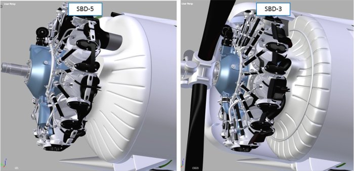
(The SBD-1 uses the same inner cowling as the SBD-3).
After this work, I had to refresh the UV maps of the modified elements. Figure 95‑11 shows my test render of the SBD-5 cowling:

As you can see, I removed the NACA cowling from this model, so that you can evaluate the ultimate result of my work.
Conclusion: as long as you can, use bump maps to recreate such panel grooves. Recreating this feature by pure modeling requires much more work (by an order of magnitude).
You can download the model presented in this post from this source *.blend file. To reduce its size, it is stripped from the texture images.

Military-Meshes.com is MIA, so following your work here.
-TeD “TuFun”
LikeLike
Welcome!
I hope that Military-Meshes will be back before this weekend (it seems that they just checking its “whois” information).
Anyway – every winter I am busy with my “daily” business, so the new posts about the Dauntless will appear in this spring… In the few free nights that I have now, I took a small side-kick project: helping to determine a more precise geometry of the Fokker D.V biplane…. I am just forming the first approximation of its shape, then I will match it againts the available photos. Maybe I will write a short post about it in March / April.
LikeLike
From what I read that’s it’s awaiting approval (Military-Meshes).
“You have reached a domain that was pending verification per ICANN rules but has since been verified. It may take 24 to 48 hours for the website to come back online.”
Enjoy reading and watching the development of the Dauntless. The detail is absolutely amazing!
I know it takes quite a bit of time to do such work so no rush on my part.
LikeLike