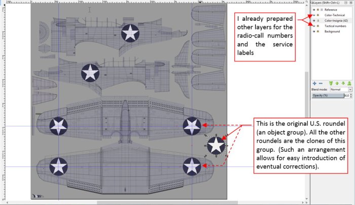
The last texture for my model contains various elements that in the plastic kits are delivered as the decals: national insignia, radio-call numbers and various service labels. I prepared it as another vector drawing in Inkscape:
I exported this picture to a raster file named color-decals.png. It has transparent background, because I will combined this image with the other components of the color texture, prepared in previous posts.
The U.S. national insignia passed various transformations during the WWII. Between December 1941 and May 1942 the roundels on the Dauntless wings were enlarged, so they spanned over the ailerons (Figure 77‑2a):

However, as you can see in the photo of the USS Enterprise deck, there were exceptions: some aircraft preserved the older, smaller roundels. After 6 May 1942 all the roundels reverted to their “standard” size (72 in). Note that in this case they did not “touch” the aileron, but still their outer edge was very close to the leading edge (Figure 77‑2b).
All of this means, that I cannot use for these wing roundels the same UV map as for the camouflage (UVMap). Although in this default UV layout the ailerons are in-line with the main wing surface (so they also fitted for the “decals” image), the problem occurs on the leading edge. In the UVMap layout its seam runs on the wing bottom surface, along the edge of the first panel. (I masked this seam on the camouflage texture in this way). Such a layout would split the bottom roundel into two parts – as marked in Figure 77‑3a):

To keep these roundels “in one piece”, I had to create another copy of the default UV layout (UVMap). I named it UVDecals. Then I modified it, adding an additional seam along the leading edge, and shifting appropriate faces from the upper to the bottom surface (Figure 77‑3b).
In fact, I created this new UV layout only for the two objects: the outer wing meshes. This is possible in Cycles thanks to a special “fallback” node. In my previous model I worked out a node group, which can deliver the default (UVMap) coordinates for the all meshes that do not contain the requested (UVDecals) map. Such a group greatly simplifies using alternate UV layouts. You can find it in the material scheme as the UVFallback node (Figure 77‑4):

Conceptually the color (diffuse) texture is composed from three images. The Decals image is placed over the camouflage (Camo), while the Dirt image is placed over them. Technically, the X.Textured Skin node internally places the decals image over the camouflage. Thus in the scheme you can see the Dirt image placed over the Camo and Decals images (it uses two Stack Image nodes for this purpose). If you want to learn more about these group nodes, see vol. III of the “Virtual Airplane” guide).
In the GIMP source, I shifted all the Stains layers from the color-camo.jpg into the color-dirt.png (see Figure 76-5 in this post). It allowed me to use the white stains layer for recreating weathering on the roundels located on the upper wing surfaces.
The stars on the wing bottom surface were also painted inside the letterbox slat. Initially there was something wrong with my UV mapping of this element (Figure 77‑5a):

The pictures of the star on the slat inner surfaces were distorted (shifted). To fix this issue, I copied current UV layout (UVMap) into the UVDecals layout, and then shifted some of its inner UV vertices (Figure 77‑5b).
Figure 77‑6 shows the first test of the “decals” texture:

At this moment it only contains the national insignia.
Now it is the time to “personalize” this aircraft. Let’s recreate the “black 4” from VSMB-241. As the first thing I added the radio-call numbers (Figure 77‑7):

The single-digit number (“4”) was painted using the standard stencil. There was no problem in recreating this detail using the USAAF stencil font. (In fact – its vertical “stroke” was shortened. To recreate such a shape, I transformed the text into path and made appropriate modification). Then I exported from Inkscape the resulting color-decals.png picture and placed it as the reference in the source GIMP image, above the Camouflage layers. Finally I painted the darker background behind the radio-call number on a separate layer, as a new part of the camouflage image.
Using the USAAF font I am able to quickly recreate various service labels. In fact, most of them disappeared from this war-weary “black 4”. On the archival photo I can see only one label, on the life raft door (above left horizontal arm of the star – see Figure 77‑7b). It is interesting to note how this detail appears on the restored aircraft:

As you can see, the labels on the restored aircraft are too large, and located in the wrong places. I recreated these elements in Inkscape, on a separate layer.
Restored aircraft can differ from the original in many details. In particular, their painting (the hue and the gloss of the camouflage, service labels fonts and sizes) leave much to be desired.
The last elements that I have to draw my “decals” texture are: the serial number (on the fin) and the model description (on the rudder). Unfortunately, the serial number is too small to be readable on the reference image, and the rudder is clipped out of its photo frame. All we can do is to use the photo of another aircraft from the same flight (Figure 77‑9a):

Among the historical photos, I had only close shots of these numbers on some SBD-5s (Figure 77‑9b). They showed me the proper font and size of these labels. For this aircraft I could only use a random serial number (Figure 77‑9c). I chose one of the lesser ones from the two polls of the SBD-3 serial numbers (3185-3384 and 6492-6701). I suppose that the aircraft from this first pool were delivered before December 1941. On the historical photo (Figure 77‑9a) of another aircraft from VSMB-241 you can still see the traces of the red and white stripes on the rudder, painted in December 1941. Then, in May 1942, the rudders were covered with the standard camouflage. You still can see these stripes behind the Blue Gray paint, because it was impossible to scratch the previous paint from their fabric skin. I reproduced this effect on my “decals” texture, drawing seven highly transparent stripes on the rudder.
Figure 77‑10 shows the final render of this “black 4”:

I also prepared for this model an alternate, sea environment:

I think that this picture of the Pacific Ocean creates a more familiar surroundings for such a naval aircraft. You can find the definition of this environment in the World tab of my Blender file. I named it Sea. Consequently, I renamed the previous environment to Land. You can easily switch between these two “worlds”.
In the next post I will work on the three-color Navy camouflage, used after January 1943 (you can find it mainly on the SBD-4s and SBD-5s). I will re-use in that new color scheme most elements from this two-color painting (the dirt texture, some of its weathering). Thus it will be a much quicker work.
In this source *.blend file you can evaluate yourself the current version of the model, and here are the Inkscape and GIMP source files of its textures. Because of the large size of the original GIMP file (*.xcf), this post is accompanied by its smaller version (2048x2048px), packed into *.zip file. I think that such a version is sufficient for checking all the details of this image (the structure of its layers, their opacities and mixing functions). The resulting textures (4096×4096) are packed into accompanying Blender file.

One thought on “Creating Textures: Markings”