In the previous post I modeled the blade of Hamilton Standard Constant Speed propeller, which was used in the SBD-1, -2 and -3. The Douglas factory mounted on the hub of this propeller a small spinner (Figure 53‑1a):

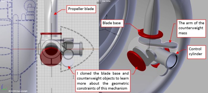
It seems that during the service of these aircraft, the ground crew often removed this spinner. It exposed the propeller pitch control mechanism (Figure 53‑1b). There are many photos of the SBD-2 and SBD-3 without spinners, thus I decided that I had also to model this “bare” variant.These constant speed propellers were in wide use during the 30’, but it was not easy to find any detailed photos or sketches of their counterweight pitch control mechanism. Finally I figured out that the counterweights were connected to the corresponding blades (Figure 53‑1c). The central cylinder shifted along the propeller axis, controlling the angle of the counterweight arm (and, in the effect — the angle of the propeller blade pitch).
By the way: this means that the overall length of the SBD Dauntless with this propeller and removed spinner depended on the current pitch setting! (I estimate that the movement range of this pitch control cylinder was about 1“). Maybe this explains the different lengths of these early SBDs, which you can find in different sources?
How to start forming such a complex shape like this variable pitch mechanism? I began by identifying its key axes and base planes (Figure 53‑2):
The most difficult part of this process is not visible here: I had to realize the basic shape of these parts. I spent some hours studying the photos before I decided that the hub (referred also as “barrel”) of this propeller can be composed from several cylindrical elements. After this conclusion I could start forming this object. I began by shaping a cylinder around the blade base (Figure 53‑3):

To facilitate my modeling, I used all of the symmetries that exist in this part. I formed just a quarter of the cylinder mesh, then mirrored it across the blade axis. In the next step I placed clones of this mesh around the two other blades. (When I modify the original mesh, it will also modify these clones).
I formed the side surfaces of this barrel from a half of an elliptic cylinder (Figure 53‑4):

I started it as a classic cylinder of a circular base. Then I rotated this object by 60⁰ and scaled it along its local Z axis until I obtained the shape resembling the photos. Then I used my Interesction add-on to obtain the intersection edge between this surface and the neighbor cylinder.
Finally I joined these two meshes and removed all of their faces. I preserved just the three edges: around the blade base, the inner edge of the elliptic cylinder and the intersection edge. I joined them with the new faces (Figure 53‑5a):

In this way I obtained a solid which looks like the original propeller hub. Note that the three segments “touch” each other without visible seams — it looks like a continuous surface (Figure 53‑5b). I used a multi-segment Bevel modifier to generate regular fillets along the sharp edges of this mesh.
I could make the opening for the counterweight arms in the front of this barrel using a Boolean modifier. However, it was relatively easy to recreate this particular shape by small modifications in the control mesh (Figure 53‑6a):

In a similar way I integrated the small fragment of the cylindrical rear axis with the rear faces of the barrel mesh (Figure 53‑6b).
The next difficult element are the flanges for the bolts that in the real propeller joined the two halves of this barrel. If I tried to incorporate them into the barrel object, it would significantly complicate its mesh. In the effect I would spent some additional hours on various adjustments. Thus I decided to create this flange as a separate object, that joins with the main body of the barrel in a more-or-less seamless way.
Figure 53‑7 shows how I shaped this element:

As in the case of the main body, I model here just a single segment of this flange — the rest is replicated by the Mirror modifier. I started from a cylinder created around the eventual bolt axis (53‑7a). Then I modified this mesh, fitting it to the underlying surface of the central barrel (53‑7b). In the next step I extruded additional “strips” of the faces that lie on the barrel surface (53‑7c). I rounded the sharp edges around these faces with a fillet (generated by a multi-segment Bevel modifier). Finally I extruded the part of the small wall that accompanies these bolt flanges (53‑7d), and shifted its origin point onto the propeller axis, to create similar flange on the opposite side of the blade base.
I created two additional clones of this object, placing them around the blade bases (Figure 53‑8a):
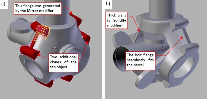
I also made the walls of this barrel thick, using a Solid modifier. Looking at Figure 53‑8b) you can see that these bolt flanges look now like integral parts of the barrel. I will recreate the remaining elements of this hub during the detailing phase (for example — the bolts that kept halves of this hub together).
The last element I have to model now are the counterweight bearing shafts. They were attached to the control cylinder. I started this part by adding a small shaft bushing on the bottom side of the counterweight arm (Figure 53‑9a):

Then I created the first row of vertical faces around this cylinder (Figure 53‑9b). I also created two additional clones of this mesh and placed them around the control cylinder, below corresponding counterweight arms. When they fit each other, I modified the topology of these faces, preparing them for joining the mesh of the shaft bush (Figure 53‑9c). Note that I placed these faces precisely below the second-last pair of the cylinder vertices. I also prepared additional faces, which will allow me to quickly join them with the octagonal cylinder of the shaft. Finally I duplicated these vertical faces, placing them on the opposite side of the shaft mesh. It allowed me to quickly create the last missing faces in this mesh, and obtaining the finished shaft bushing object (Figure 53‑9d).
Figure 53‑10a) shows the complete pitch control mechanism of the constant speed counterweight propeller:

I will add more of its details (the bolts, for example) during the last phase of this project. In the last step I also recreated the spinner (Figure 53‑10b). It was an easy solid of revolution — I will not elaborate here how to create it. (If you want to learn more about shaping the spinners — see this guide). There is one missing thing: I do not know how this spinner was attached to the propeller hub. Do you have any hint on this subject?
In this source *.blend file you can evaluate yourself the model from this post.
I will create the R-1820 engine during the detailing phase. This was the last element of the SBD-3 that I created before the UV-mapping and texturing phase. (In fact, I am not going to unwrap the small elements of the variable pitch mechanism. I could just create the propeller blades and the spinner. I created it just because this propeller hub is a quite large part of the Dauntless silhouette). In next post I will recreate the few details which differ the SBD-1 from the SBD-3.
