In this post I will create internal structure of the upper split flap. Structures of both flaps are similar, thus I started this job by copying stringers from the bottom flap, finished in the previous post (Figure 16‑1):

Every copied stringer is a duplicate of its counterpart from the bottom flap (I just used the negative scale: -1). I had to rotate these objects, placing them on the internal side of the upper flap skin. I copied the internal ribs in the same way (Figure 16 2). (All of them are clones, which use the same mesh):

As you can see in the side view (Figure 16‑2 upper left), there is just a small vertical distance between the last ribs of the upper and lower flap (i.e. at the aileron). This is the thinnest place of this structure.
At the trailing edge of the upper flap there is the profiled wedge (I described it in the previous post). The upper flap is little bit wider (it has longer chord length than the bottom flap). Because of this the ribs of the unified size used in these flaps are too short to reach the closing wedge (Figure 16‑2).
We can observe this effect on the photos. To make these ribs longer, designers added at their ends small “U”-shaped profiles (Figure 16‑3):

I recreated these elements in my model (Figure 16‑3, right).
The upper flap has a cutout in its inner edge. Thus there is “one and half” of the external rib here (Figure 16‑4):

I recreated this structure in my model and modified the mesh of the upper skin (Figure 16‑5):

These flaps were attached to the wing by two long hinges. I recreated them as two very long cylinders and placed between the flaps and the wing (Figure 16‑6):

These hinge objects will play important role in the future animation of the flap movement. At this moment I organized all these elements into a hierarchical structure. I set the hinge as the parent of the flap skin object, and the flap skin as the parent of all the ribs and spars (Figure 16‑6, right).
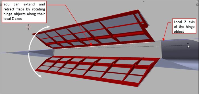
Now, when I rotate the hinge along its local Z axis, the whole flap rotates, like in the real aircraft (Figure 16‑7):

This is a preparation for the future animation of this movement (during the detailing phase).
In this and the previous post I built flaps and their basic skeleton. I recreated these ribs and stringers because they are visible when the flaps are extended. The additional benefit of this work was the verification of my reference drawings. (Now I know that I have to shift a little the perforation and rivet seams on both flaps. I will do it when I prepare their textures). However, on this stage it is too early to finish all remaining details of these flaps. It still may happen that I will discover something which will force me to modify the geometry of this wing and its flaps. Thus in Figure 16‑8 I marked what I prefer to postpone until the detailing phase:

As you can see in this picture, I will create the openings in the flap skin later. At this moment I am going to recreate them using the same technique as for the lightening holes: textures (the bump map and transparency map). However, if this idea fails, I will model these openings in the flap skin mesh. (This method requires much more time than the textures).
In addition to these openings I will also recreate all the minor details of the flap structure. For example — I will split the “L”-shaped auxiliary stringer between the ribs. I have also to split the flap forward reinforcements into separate segments.
The complex system of the flap actuators will be also a challenge for the detailing phase (however, I already analyzed how it works).
In this source *.blend file you can check all details of the model presented in this post. In the next post I will create the fixed slats and finish this outer wing panel for this “general modeling” stage of work. Of course, I will work on it again later, during texturing and detailing.
In the next post I will add fixed slats, completing this outer wing section.