Perforated split wing flaps were the hallmark of the SBD Dauntless. Their inner side was reinforced by the “grid” made of stringers and ribs. Because these flaps were often wide open — during landing or in dives — I have to recreate their internal structure. In this and the next post I will describe how I did it.
All the SBD flaps had fixed chord (they were made from perforated sheet metal of rhomboidal shape). After studying many photos I assume that all their ribs have the same size and shape — also the parts attached to the trapezoidal, outer wing section. It seems that Douglas factories built all five flaps of the SBD in the same way, using unified components. The flaps for the external wing panels had to be twisted a little during riveting — most probably on appropriate mounting pads. The trailing edge of the upper flap is the trailing edge of the whole wing. It was a thin wedge, profiled from a sheet metal and riveted to the flap skin (Figure 15‑1):

(Similar wedge is riveted to the upper skin of the center wing — see Figure 15‑1). The chordwise contour of these flaps looks flat on the photos. In fact there is only a small difference (less than 0.2 inches) between the theoretical contours of the wing airfoil and a straight line on the area around the trailing edge. I think that for the designers such a technological simplification was not a big deal — they had already made a more serious modification by perforating the flaps.
I started building the SBD flaps by creating their upper and lower planes. (I created them by simplification of the mesh fragment that I previously cut off from the wing). I used the Solidify modifier to give them thickness of a sheet metal. (I used this modifier for all parts which I will create in this post). Then I added the wedge (another object) along their trailing edge (Figure 15‑2):

I started this wedge as a single contour, which I extruded along the whole span of the flap. Because of the trapezoidal shape of this wing, I had to twist a little the outer end of this wedge, fitting it better to the upper flap. Then I shortened the trailing edge of the bottom flap, fitting it into the wedge when it is closed.
When it was done, I added the main “spar” of the flap (in fact it was a U-shaped stringer). I did it in the same way as I created the trailing edge: shaping the profile, then extruding it lengthwise (Figure 15‑3):

Once extruded, I had to rotate this object and twist its end, lying its outer edges on the inner surface of the flap skin. To facilitate this process I assigned this object a contrast, red color.
While fitting this spar, I discovered that the twisted, four-vertex face of the flap skin has small elevation along its diagonal (as in Figure 15‑3). It is not something “real” — just an effect of the internal decomposition of all quads into triangles made by Blender.
To eliminate this artificial effect I had to divide this sigle, large face into several smaller pieces (Figure 15‑4):

It minimized the influence of Blender internal “triangulation” and allowed me to properly fit the stringer to the flap. As you can see in Figure 15‑4, the end profile of this spar is twisted, following the twist of the flap skin.
After the first stringer I created in a similar way two other reinforcements on the flap edges (Figure 15‑5):

As you can see, I used two clones of the rib contour. (I needed them to determine slopes of the front and rear reinforcements in the side view — as in Figure 15‑5).
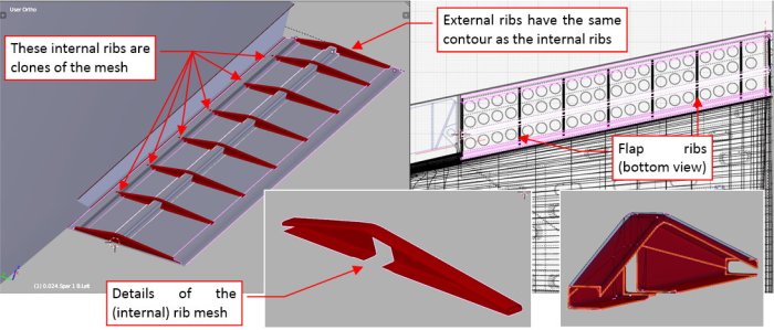
When the flap lengthwise reinforcements are in place, I can add the ribs (Figure 15‑6):

All the internal ribs are clones of a single mesh. The external ribs have the same contour, but each of them has its own mesh (because they do not have the cutout for the central spar, as the internal ribs). These flap ribs have quite complex shape, but I managed to keep their mesh quite simple. It was possible, because a part of this complexity (the sheet metal thickness, rounded edges) is created by the Solidify and Bevel modifiers.
When the ribs were in place, I added the last stringer. It was a “L”-shaped beam (Figure 15‑7):

Modeling internal structures of the flap forced me to carefully measure anew all of its details, especially the width and location of its spars. In the effect you can see that my wing drawings are not as precise as you could expect (Figure 15‑8):

In this source *.blend file you can check all details of the model presented in this post. In the next post I will continue my work — this time on the upper flap.
3 thoughts on “Modeling Wing Flaps (1)”