This Monday I finally got the “Instructions for the Erection and Maintenance of the Model SBD-6 Airplane” book – more than 600 pages about the Dauntless, published by Douglas in March 1944. Because of the lengthy title, I will refer to this book as the “SBD Maintenance Manual” or the “Douglas manual”. In spite that it describes the last produced version, it is also usable for the earlier models: as I mentioned in one of the previous posts, the SBD-1 airframe behind the firewall differs only in a few details (the double gun mount, gunsight type, lack of the YAGI antennas) from the SBD-6.
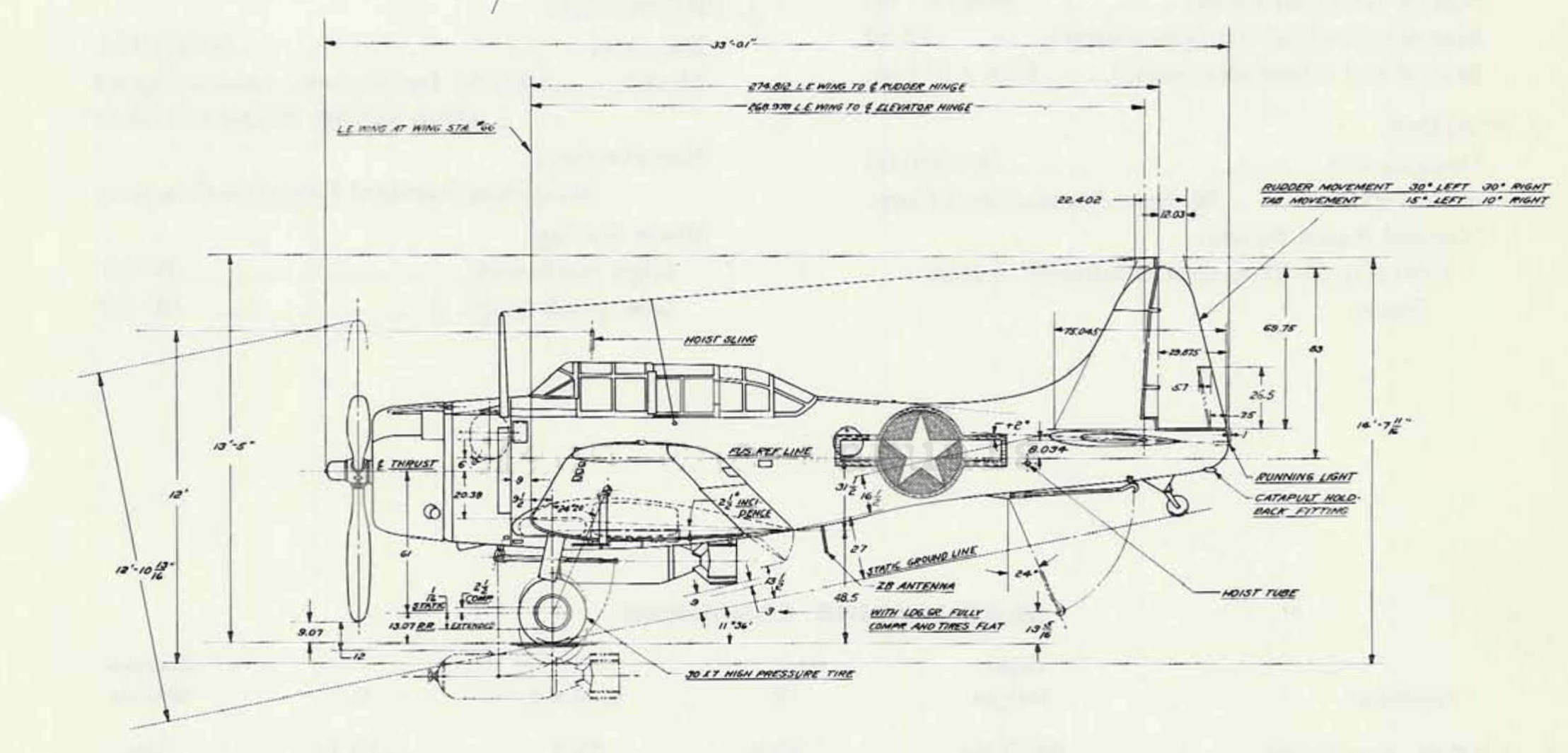
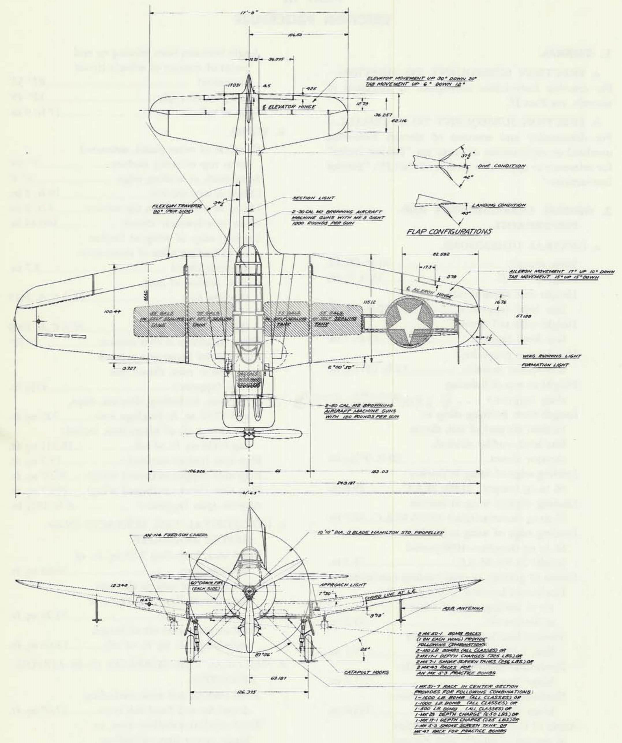
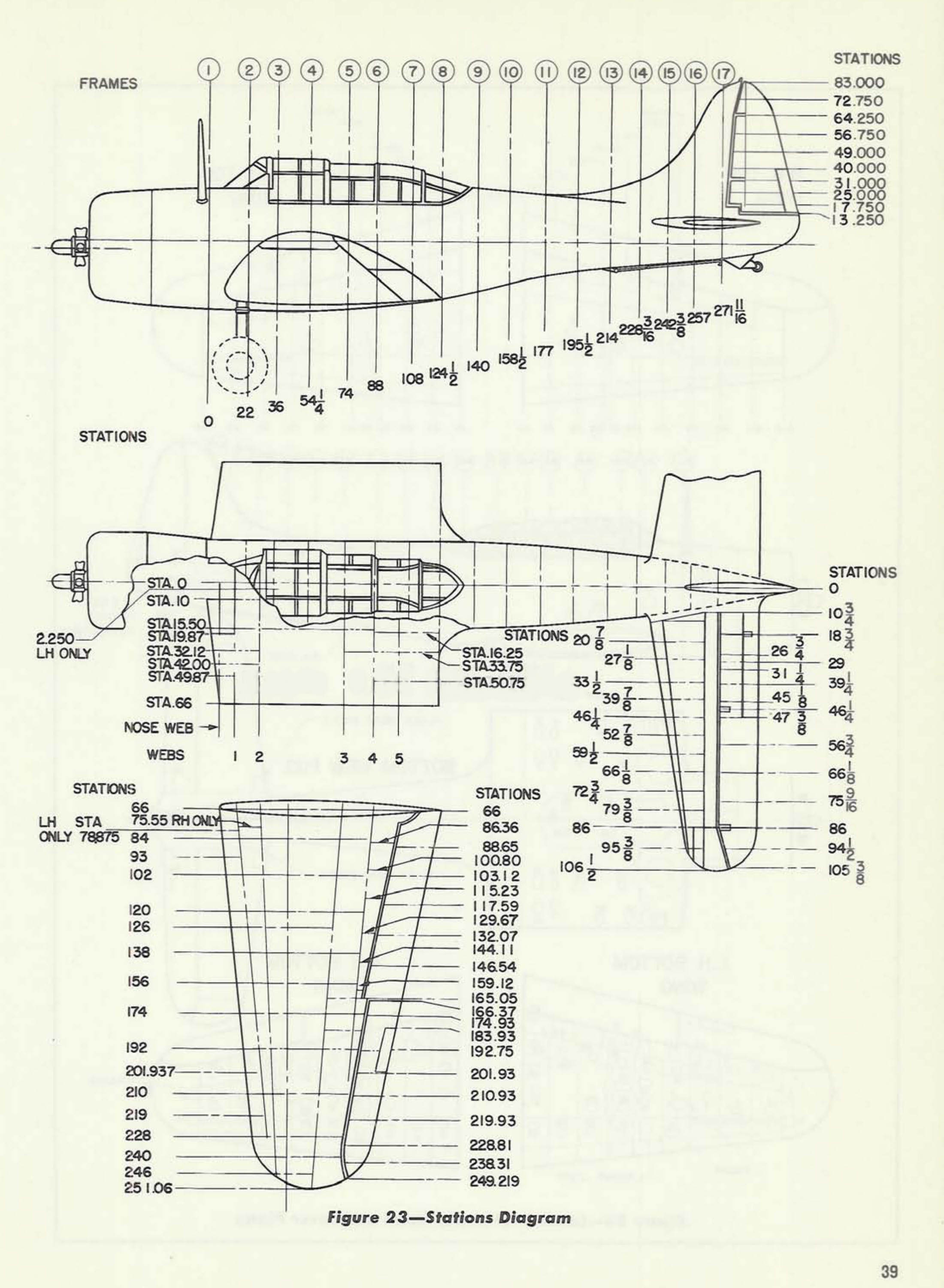
Inside you can find the SBD-6 general arrangement drawings, as well as the stations diagram (Figure 6-1):

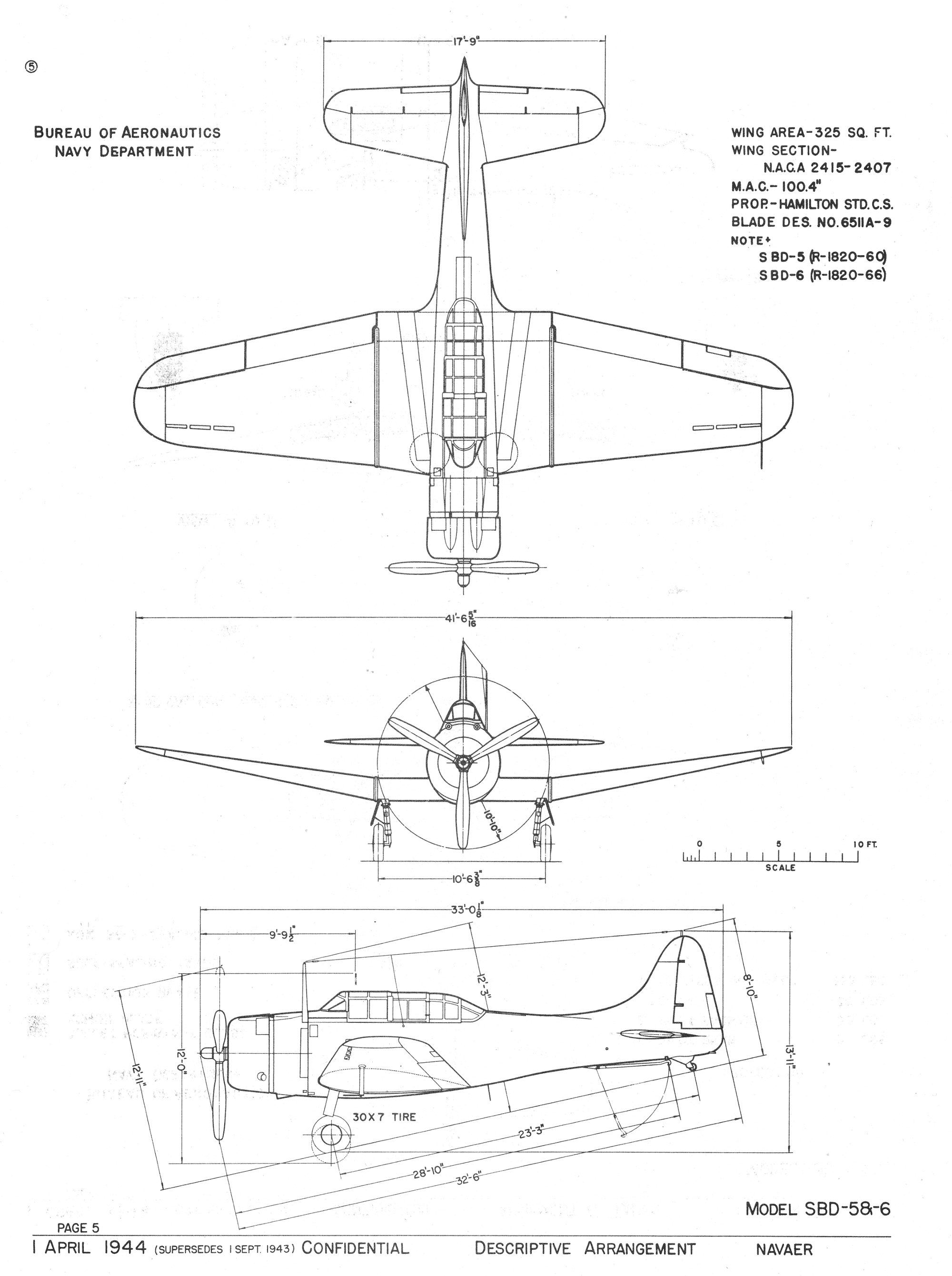
Here are the links to the high-resolution versions: side view (cropped from the page), top and front view, and stations diagram. As you can see these Douglas diagrams contain more dimensions than the BuAer drawings. Their chains on the side view allow for verification of the wing location, as well as the wing and tailplane incidence angles. They also allow you to determine the basic “trapeze” around the rudder and the fin. From the front view you can also read the dihedral angle of the outer wing panels (9⁰ 19’).
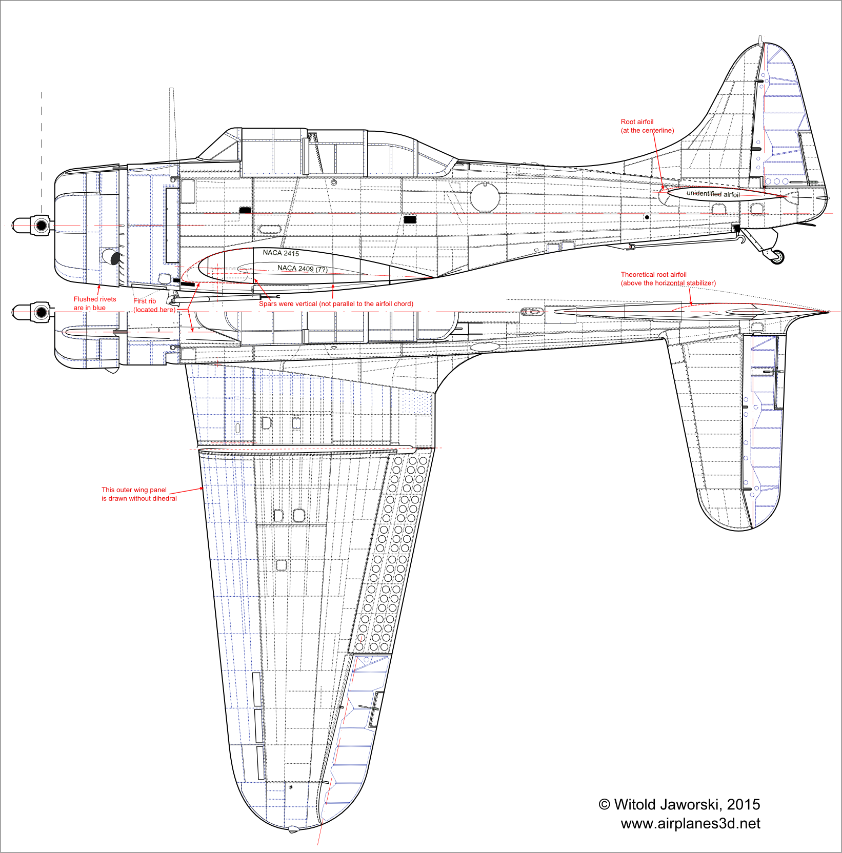
The dimensions from the top view allowed me to draw the basic trapezes around the wing and tailplane, as well as to determine locations of the aileron and elevator hinge axes. This information, combined with dimensions from the side view, allows for determining the precise location of the firewall, wings and empennage. I used them to verify my scale plans. Sometimes they just confirmed what I determined before (for example — locations of the wing or the last bulkhead). Sometimes they revealed the errors I made. I will write more about it in the next post. So here is the current, updated version of my drawings (Figure 6-2, Figure 6-3):

Because of the formatting issues I had to split this image into two parts:

(Click here to get these drawings as a single, high-resolution image). Note that I draw the outer wing panel without its dihedral (it is much easier to build its model using such a “flat” reference). Thus when you check proportions of this top view, its span/length ratio is somewhat greater than the expected value of 41’ 6” / 33’. What is interesting, the dimensions on the general arrangement drawing indicate that the “official” wing span does not include the size of the running lights (Figure 6-4):

To obtain the “physical” wing span value you have to add 1.5” to each wing. I used similar convention when I matched the fuselage contour against its dimension (33’ 1/8”). These dimension lines are more obscured on the side view, but for the matching purposes I skipped the length of the running light cover protruding from the tip of the tail (1”).
In general, after all these updates I feel more confidence in my drawings. I know which elements come from the explicit dimensions of the general arrangement diagram, which from the photos, and which are based on other drawings or just on an assumption. The only larger element that I was not able to verify is the fuselage width (i.e. its contour in the top view). It is copied from the Douglas drawing. I was able just to verify it at the 9th bulkhead (station 140). I have a photo of this bulkhead from one of the Dauntless restorations, so I am sure that it fits properly into the fuselage contour on both views: the side view and the top view. However, I did not verify in any way the curved contour of the tail on the top view.
Frankly speaking, after this experience I am really glad that I am doing such a “slow start” to the modeling by preparing these drawings. It forced me to think twice (or even more times than twice) about every part of this airplane, resulting in better understanding of various nuances of its geometry. Sometimes I had to deliberate over a single line (like the gap between the elevator and stabilizer) for a whole day, watching and comparing hundreds of photos. In the effect I had to move a few lines around it on the plans. It was not a big deal. However, if I already started to build the model, adaptation of such findings would require a lot of work!
In the next post I will tell you more on how I used the explicit dimensions from the Douglas drawings. They allowed me to find a flaw in my plans. Description of this case will give you an insight into the errors that you can make using the photos.

Excellent information. I’m able to apply it directly to my own F-100 project, where I’ve just come across the manufacturer’s station diagram drawing in a structural repair manual.
Witold, if you get a chance, somewhere in a future blog, I’d be interested in reading why you’ve selected the Dauntless as your current project.
Thanks for documenting this build!
LikeLike
Brian, tomorrow and next Saturday I will publish two detailed post how I used these materials to draw the top view – I hope that you will find them useful for your F-100!
Why did I selected the SBD Dauntless? – Well, just a sentiment. This simple, rugged aircraft was like a good, reliable soldier. It was built in comparable numbers to the famous Ju-87, but had the luck to be used for the better cause (it did not destroy cities, as the Ju-87 did). And, of course, the SBD Dauntless had its 5 minutes during the Midway battle – I do not remember any other airplane which had such a decisive role in any other battle.
LikeLike
Your’s is an interesting perspective I’ve never considered: The Slow But Deadly (SBD) had the same method of attack as the JU-87, but lacks the “terror” reputation of the Stuka, presumably because, as you say, it generally didn’t fight land battles against population centers. I’ve also always thought the JU-87 looks somewhat evil, with all its sharp, angular features and dark camouflage, whereas the SBD, being blunt and knobby all over, and blue, looks like something you’d find at Disneyland. Pilots also really liked the Speedy, and preferred it to its successor, the Curtis SB2C Helldiver. Pilots hated the Helldiver. What a nasty piece of excrement. The Helldiver’s successor, on the other hand, the A-1 Skyraider, is in my opinion the highest expression of the piston-powered attack airplane. Ed Heinemann designed both the SBD and the A-1, the latter after spending time in the South Pacific in 1943 on a fact-finding tour learning first hand how the SBD faired in combat. You can deduce the shortcomings of the SBD configuration by comparing how it differs from the A-1.
LikeLike
Yes, in fact the Helldiver had some serious flaws, for example: flaps powered by independent electric engines. They were not reliable, and could fail (of course – only one of them!) during landing. The immediate effect was a crash of the airplane because only one flap had extended… In the post-war versions they replaced them with hydraulic actuators.
I did not know that the Skyrider was also designed by Ed Heinemann, I have to read more about it!
LikeLike
Thanks! Useful … .. (-___________-)
LikeLike