Reviewing the original P-36/YP-37/P-40 blueprints published by AirCorps Library, I also browsed the “uncategorized drawings” category. In general, many Curtiss drawings from this microfilm set are unreadable, especially these “uncategorized” images. Often all what you can see is just a blank microfilm frame with barely visible remains of the title block. However, in this “junk” category you can find interesting sketches of various design proposals. One of them is the YP-37 with the powerful R-2600 Twin Cyclone engine. Below you can see side view of the initial idea, from November 1938:
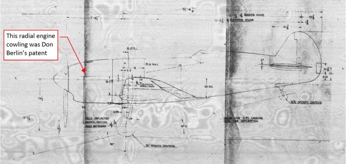
(Here you can download the complete P-1660 drawing). The Curtiss-Wright R-2600 engine (1600hp) offered 40% more power than the inline Allison V-1710 (1150hp), used in the YP-37 prototypes. However, this additional power was gained at the price of additional weight (R-2600 dry weight was 2045lb against the 1400lb of the V-1710). In this aircraft this radial engine was covered with a special cowling which resembled cowlings of the inline engines. It was a patent of the chief engineer, Donovan Berlin. Below you can see another Berlin’s prototype – XP-42, in which he used similar cowling for the two-row radial R-1830 engine:

Basically, the XP-42 “inherited” everything behind the firewall after serial P-36, in the same way as the aircraft from drawing P-1660 inherited the airframe after the YP-37. I also found inboard profile of this YP-37/R-2600 proposal (drawing P-1661):

(Here you can download high-resolution version of drawing P-1661. I composed this image from three subsequent microfilm frames). Like the YP-37, this fighter would be equipped with a turbo-supercharger, which delivered compressed air to the engine carburetor (via an intercooler). When I analyzed this drawing, I wondered about the purpose of a strange empty space between the engine and the oil/auxiliary fuel tank. Fuselages of fighter planes were usually packed with fuel, ammunition, and other equipment, thus it was quite unusual to leave such a plenty of useful space close to the aircraft mass center! You could put there another fuel tank, or a pair of 0.5 cal. guns with large ammunition boxes…
This design also inherited after the YP-37 the extremely poor forward visibility during taxiing. It could be much worse than in the later F-4U or even than in the original YP-37, because in place of the sleek inline engine you had a much wider radial powerplant.
Another design flaw soon became apparent thanks to the first XP-42 tests, conducted in the beginning of 1939: Berlin’s cowling did not cool properly the radial engine cylinders. The small air scoop, which you can clearly see in the XP-42 photo below, did not provide enough air for 2×7 cylinders used in the R-1830:

Thus Curtiss engineers prepared another proposal. I found it on drawing P-2131, dated on 10th April 1939, titled “two stage icing nose”:
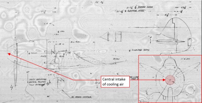
(Here you can download the complete P-2131 drawing).
This time they proposed a cooling air scoop in the middle of the spinner – an idea also adopted in the Focke-Wulf FW-190 prototype, designed in the same time in Germany:

However, there was a significant difference: Focke-Wulf engineers placed a fan behind the propeller. This fan rotated three times faster than the propeller blades. It “pumped” additional amount of the cooling air onto the cylinders of the BMW-139 engine:

Even with this modification the first series of the FW-190 faced troubles with overheating second cylinder row. In late 1940 the whole FW-190 project was almost cancelled due to these issues. What is interesting, they were finally resolved not by the Focke-Wulf design bureau, but by Luftwaffe field technicians.
At the end of 1940 Luftwaffe created an experimental unit in France for field evaluations of the pre-production FW-190 A-0s. These aircraft were equipped with a more powerful BMW-801 engine and a classic engine cowling with small spinner. Early FW-190s were plagued by the overheating engine cylinder issues. Technicians from this unit experimented with various cylinder deflector shapes, ultimately finding a solution for effective cooling.
Thus – most probably the design from drawing P-2131 was doomed from the start, because of the engine cooling problems.
I also found inboard profile of this YP-37/R-2600 variant (drawing no P-2133):

(Here you can download high-resolution version of this profile). For this aircraft designers proposed a R-2600 engine with two-stage mechanical supercharger. Compressed air from the first stage was cooled in a large intercooler, then directed toward the carburetor, placed before the inner (second-stage) supercharger. The inboard profile reveals that first stage of the supercharger could be turned off, and additional air scoop could direct the outer air directly toward the carburetor and the inner supercharger. This air scoop is marked on the drawing as “cold air”.
In overall, this solution was simpler than the first, turbo-supercharged variant, but still quite complex. The engine proposed in this variant was most probably the R-2600-B (1800hp at take-off).
There is also the last, third YP-37/R-2600 variant, depicted in drawing no P-2193 (dated on 28th April 1939):

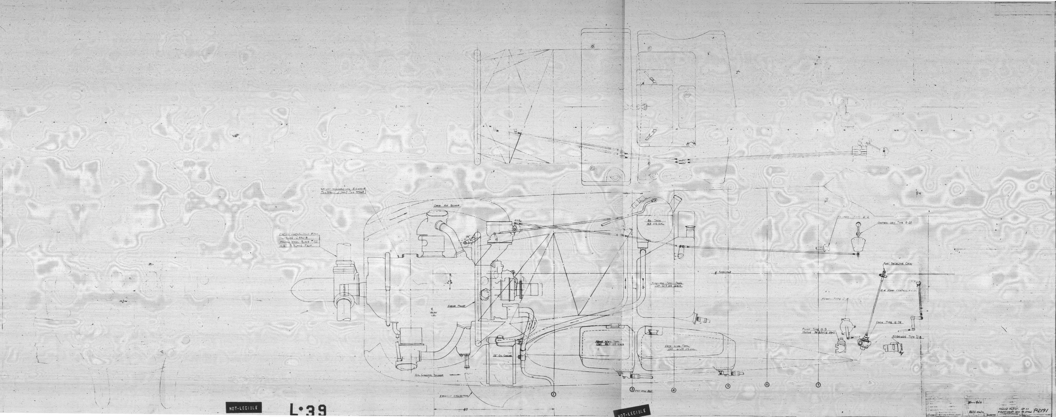
(Here you can download the complete P-2193 drawing). This aircraft is named “short-nose”, because it uses a classic NACA cowling around the short-geared R-2600 engine. It seems that this is the standard production engine featuring single stage, two-speed inner supercharger, rated at 1700hp (similar engines were used in the A-20s). Drawing P-2191 reveals internal details of this powerplant installation:

(Here you can download high-resolution version of this profile). This is the simplest solution: you can see in this drawing just a straight carburetor air scoop, without any additional supercharger or intercooler. In the result, an empty, unused space behind the engine is back!
What about the possible performance of the YP-37/R-2600 fighter? Could it be significantly better than the YP-37, or its direct predecessor, the P-36?
Well, we can estimate the answer basing on other aircraft designs in which similar inline engine was replaced by a similar two-row radial. For example – such a thing happened to the Soviet LaGG-3 fighter which used 12-cylinder M-105P inline engine (improved version of the Hispano-Suiza) rated at 1100hp on takeoff. In 1942 it was replaced by 14-cylinder, two-row radial M-82 engine (which closely resembled R-2600) rated at 1700hp on takeoff. The result was named La-5. Below you can see inboard profiles of both aircraft:

The LaGG/La airframe was 20% smaller than the P-36/YP-37/P-40 (its wing area was 187sq. ft, comparing to 236 sq. ft of the Curtiss fighters). The max. takeoff weight of the LaGG-3 (1941/42 variant) was 7 270lbs. Its max. speed was about 342mph at 16 000ft, and time to climb to 16 400ft was 7.4min. Takeoff weight of the La-5 (first series) was 7 450lbs. It reached 360mph at 21 000ft, and time to climb to 16 400ft was 5.7min. Note the minimal increase of the takeoff weight: it seems that the weight of the radial M-82 engine (dry: 2050lbs) was comparable to the weight of the M-105P coupled with the necessary cooling liquid installation (mainly the large radiator).
The new engine mounted in this Soviet airframe improved its climb rate by 23%, while the maximum speed increased by 5%-8% (depending on the altitude). Note that in spite of their smaller size, the weight of these LaGG/La was comparable to maximum weight of the YP-37. Generally this is because these LaGG/La were equipped with self-sealing fuel tanks, armor plates, and carried much more armament than the YP-37. In addition, they were made of plywood – which made these fighters somewhat heavier, but much cheaper (i.e. easier to produce) than the classic all-metal riveted airframe. (One of the factories assigned to Lavochkin’s bureau, no. 31 located in Tbilisi, was a former furniture manufacturer).
Taking into account the performance of the Allison-equipped YP-37 (rated at 1090hp on takeoff), as well as the XP-40 and P-40-cu, one could expect similar improvements from the “short-nose” YP-37/R-2600. I estimate that its takeoff weight could be about 7 200lbs (without the self-sealing tanks, and armor). For this weight, it could reach 15 000 ft in 4.5min, and obtain the maximum speed of about 370-380mph. The climb rate would decrease after adding the additional weight of the armor and self-sealing tanks (by about 10%), while the maximum speed could be preserved tanks to introduction of a more smooth, flush-riveted skin. (It was introduced in the P-40-cu, increasing its speed by about 10-15mph). Of course, the maximum range of the R-2600-powered aircraft without external fuel tanks would be shorter.
The YP-37/R-2600 project seems to be a typical example of the simple engine upgrade. The engineers put a new, more powerful engine into the existing airframe, without any additional improvements. The new radial engine increased the area of the fuselage cross-section, in the effect producing more drag which “consumed” certain part of the increased engine power. Usually the length of the “inherited” landing gear legs in such designs restricted propeller diameter to a sub-optimal size. (The more powerful engine requires larger propeller. For example – the diameter of the F4U propeller was 13’ 2”. Curtiss for this YP-37/R-2600 planned a 11’ 6” propeller, but it already seems too large, leaving just 5’ clearance between the blade tips and the ground).
Let’s look at different case: how much you can improve aircraft performance when you increase engine power without changing the airframe geometry and its weight? In 1939 Curtiss introduced such a modification to the P-36, upgrading the R-1830-13 engine used in the P-36A (rated at 1050hp) to a more powerful variant: R-1830-17, rated at 1200hp on takeoff. The design changes were minimal: this new engine variant used a 100-octane fuel, while the previous variant used 92-octane fuel. This change increased the maximum engine power at takeoff by 15%. The new model was named P-36C:

The maximum speed of the P-36C increased by 11mph, to 311mph at 10 000 feet, (3.5% improvement comparing to the P-36A). Without the additional wing guns and ammunition (they added 140lbs to the total weight and generated additional drag) it could reach 313mph (4% improvement). In the ideal case the maximum speed should increase by cubic root of the increase of the engine power, which means 4.5%. (At 300mph you can still neglect the effects of the air compressibility). However, this ideal case would require somewhat larger propeller, while the P-36C used the same propeller as the P-36A (10’ in diameter). The climb time to 15 000ft slightly degraded in the P-36C to 4.9 min instead of 4.8min in P-36A, most probably because of the increased weight (max. gross weight: 6 150lbs, while in the P-36A it was 6 010lbs).
Finally let’s analyze opposite case: instead of the engine upgrade, what results you can obtain from the same/similar powerplant, using various minor improvements? (For example – aerodynamic enhancements)?. There is an interesting historical evidence on this subject. In September 1940 Pratt & Whitney Aircraft Division bought a complete P-40-cu airframe (precisely: H81A-1, less the engine). Practically, it was a somewhat heavier, flush-riveted variant of the P-36 airframe. In this aircraft Pratt-Whitney engineers carefully mounted the R-1830-SSC7-G engine. This high-altitude variant featured two-stage mechanical supercharger. (I suppose that similar engine was used in the F4F-4 under the military symbol R-1830-86. However, this SSC7-G variant was tuned for even higher altitudes than the “Wildcat” engine). It was rated at 1200hp on takeoff – just like the R-1830-17, used in the P-36C.
This was not a high-priority project, and the aircraft was finally ready in mid-1942. You can see it in the photo below:

As you can see, Pratt-Whitney engineers completely redesigned the powerplant section, up to pilot’s cockpit. The side outlets of the engine cowling resemble a little bit those in the FW-190. Because in the R-1830 carburetor was mounted on the top of the rear crankcase, I suppose that the upper air scoop visible on this aircraft cowling is the carburetor air intake. However, it seems to be too large for this solely purpose. Maybe it was also used for additional cooling of the rear cylinder row?

[2020-02-25 update: The increased upper air scoop was most probably used by the engine carburetor and the intercooler, located after the first stage of the supercharger. You can find similar intercooler in the F4F. MIflyer, thank you for pointing this!]. Note also that Pratt-Whitney introduced an antenna mast – because the slanted radio wires used in the serial P-36 and P-40-cu/B/C generated a lot of unnecessary drag! (Starting from the P-40D Curtiss also introduced antenna masts to their design). For this aircraft Pratt-Whitney developed an exhaust system which provided jet propulsion effect. Similar solution was used in German Focke-Wulf FW-190 and – later – in Soviet La-5FN. In this system each cylinder has its individual exhaust stack, and these stacks run in parallel on both sides of the engine cowling. (There was no exhaust collector, used in the classic designs). It was an important improvement: in each of these fighters it increased the maximum speed by about 20mph. The gross weight of this aircraft was 7 100lbs (so it was 1 000lbs heavier than the P-36C, while the eventual self-sealing tanks, armor, and wing guns would further increase this weight to 8 300lbs).
Nevertheless, this P-40/R-1830 could reach 388mph at 25 000ft (at this altitude its engine still maintained 1015hp in the “military” power mode). This is an excellent result, when you compare it to the 311mph of the P-36C. Pratt-Whitney calculated that for the fully-equipped aircraft weighting 8 300lbs it would decrease by 10mph, to about 378mph. Of course, you can argue that this aircraft featured a special, high-altitude engine variant, so it could reach this speed in the area where P-36C already lacked power. Thus a better choice for the just comparison between the P-40/R-1830 and the P-36C is the maximum speed at the sea-level, where the output of both engines was identical (1200hp). The P-36C reached 272mph at sea level, while the P-40/R-1830 – 315mph. (43mph more! An increase by 16%). However, I suppose that the climb time to 15 000ft of the Pratt-Whitney aircraft would be worse than in the case of the P-36C, because of the greater weight. I estimate that for the “military” weight of 8 300lbs it could be comparable to the P-40F: 6.9 min. (In 1942 this result was “below the average” for a new design).
When this aircraft appeared, production of the Allison-equipped P-40K and the Merlin-equipped P-40F was in the full run. The performance improvements offered by the P-40/R-1830 were not a “breakthrough”, and in the 1942 the undisturbed output of the Curtiss fighters was critical to the war effort. (In 1942 serial P-40Fs reached 370mph at 20 000ft. Switching production to such a new variant as the Pratt-Whitney prototype would slow down the existing output from the Curtiss factory. In that time it was better to immediately dispose a dozen of even sub-par aircraft like the P-40F or P-40K, instead of waiting for improved fighters in the future. On the other hand, in that year other suppliers already begun full-scale production of more promising projects like the P-38, P-47, P-51B, F6F and F4U). Thus, further work on this Pratt-Whitney P-40 was discontinued in mid-1943.
Do you wonder, what kind of aircraft could be created if Curtiss would apply in 1939 the exhaust jet propulsion effect to their YP-37/R-2600 project (as did Kurt Tank in the Focke-Wulf FW-190)? Well, I do not expect that it would be useful in the incoming war, anyway. The main disadvantage of this design would be limited capacity of the YP-37/P-40 fuel tanks. Increased fuel consumption of the R-2600 engine would restrict its maximum range, which was just average with the less-powerful Allison inline engine. Even in the case of the R-2600 mounted in the P-40 airframe, there would be no remedy for this issue. (In the P-40 pilot’s cockpit was located just behind the firewall, thus it already used the empty space I marked in my drawing for the fuel tank placed behind the cockpit. The space in the P-40 wings was already used in by the landing gear and guns). In the best case such a P-40/R-2600 would be shipped as a lend-lease product to the Soviet Union, as it happened to the P-39. (The Eastern Front was the only WW2 area where the fighter range capability was not a key issue – most of the Soviet fighters had enough fuel for less than one hour of combat mission).
However, the Pratt-Whitney P-40/R-1830 design is an evidence how much the final result depends not only on the funds allocated to the project (I suppose that Curtiss in 1941-42 had enough money at hand), but also on the quality of the engineering team. It is interesting that in the same year – 1940 – the North American team took similar challenge and designed “a better P-40” (the “Mustang”) which initially featured the same engine and wing area as the Curtiss design. However, they did it quickly, for a powerful project sponsor (British RAF). We can only speculate, what could happen if the Pratt-Whitney project received similar boost and delivered this aircraft after one year, instead of two (i.e. in 1941, instead of 1942). Maybe it could be put into production in place of the P-40D? In that year the P-40/R-1830 performance could be considered as much better alternative than it was in 1942…
Anyway, it seems that since 1940 Curtiss engineers could not “catch-up” with the general progress in the aircraft development. This finally led to the general decline of the entire Curtiss Aeroplane Division. In 1948 it was sold to North American Aviation.

Curtiss proposal to Navy in 1938 competition was a P-36 powered by R-2600 with top speed of 370-377mph. Navy went with Corsair.
LikeLike