In this last post about scale plans I will write about the modifications introduced in the SBD-5 Dauntless version.
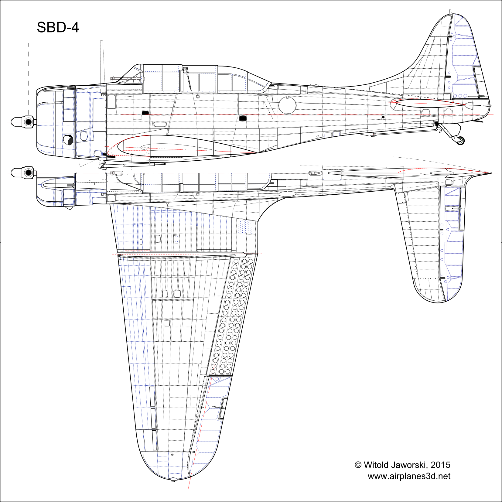
For the reference, I placed below the drawing of the previous version: the SBD-4 (Figure 11‑1):

(See the high-resolution SBD-4 left & top view).
In February 1943 Douglas started to produce another Dauntless version: the SBD-5. It used more powerful Wright R-1820-60 engine (performing 1200 HP on takeoff: 20% more than the R-1820-52 used in the SBD-4). The engine was moved a few inches forward, and the whole area in the front of the firewall was redesigned (Figure 11‑2):
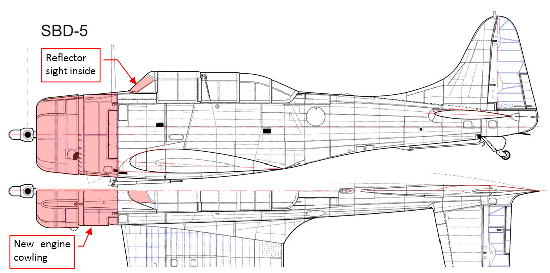
The old telescopic sight was replaced by modern reflector sight. The SBD-5 had heated windscreen (because it sometimes misted over in dives). (See the high-resolution SBD-5 left & top view).
The engine in the SBD-5 was moved forward by 4 inches, together with its NACA cowling. The overall shape of the NACA ring was the same as in the previous versions, except the removed carburetor air scoop. (The cross sections A in Figure 11‑3 are the same in both versions):

The shape of the firewall (section C in Figure 11‑3) remains unaltered. However, there is a difference in the width of the gap behind the NACA ring. In the SBD-1 … 4 this gap was relatively narrow, and the cross section of the fuselage below (section b in Figure 11‑3) forms a regular ellipse. Thus in the previous versions the upper part of the NACA ring had six flaps. They controlled the flow of the cooling air through the engine. In the SBD-5 the fuselage was a little bit “thinner” here, and the bottom part of its cross section (section B in Figure 11‑3) had slightly different shape. The larger gap between the NACA cowling and the fuselage increased the constant amount of the incoming air that cooled the engine. It allowed Dauntless designers to reduce the number of cowling flaps from 6 to just 2.
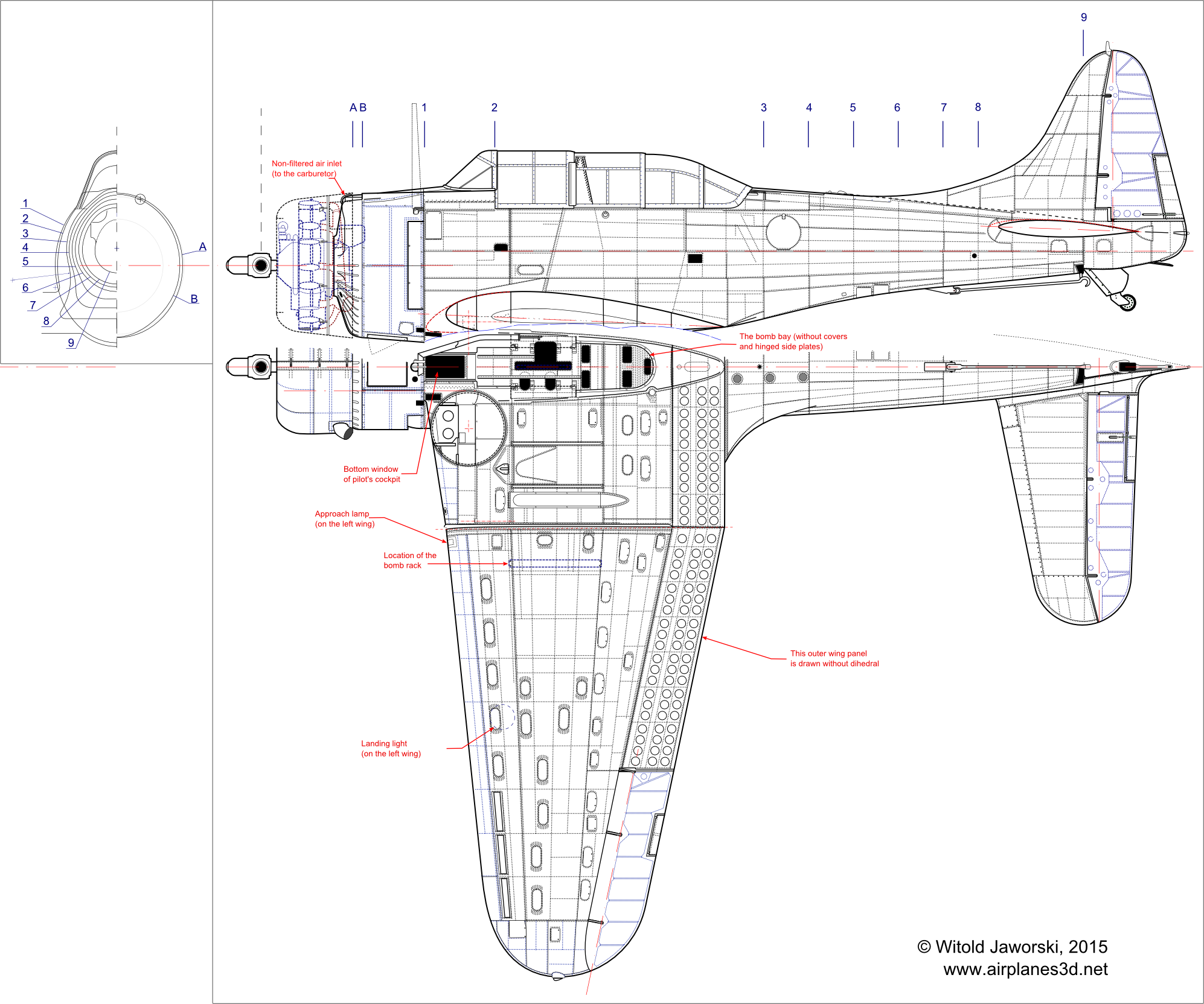
Figure 11‑4 reveals more differences between the SBD-4 and SBD5 engine cowling:

(See the high-resolution SBD-5 bottom view).
Some of these changes are well known, like the removal of carburetor air scoop from the top of the NACA cowling or the different shape of the side ventilation slots. However, while studying the photos, I have found two minor differences that were not yet mentioned in any source:
- The oil radiator air scoop was in the SBD-5 was wider than in previous versions (as well as its panel);
- The bottom seam of the NACA cowling was in the SBD-5 shifted left, while in the previous versions it was running along the symmetry plane;
Finally, I would also like to share with you my findings about the carburetor air intake in the SBD-5. As I mentioned earlier, it disappeared from the cowling, as you can see it on the front views in Figure 11‑5:

(See the larger SBD-5 front view).
But where did they place this air scoop in the SBD-5? Studying the photos and descriptions in the books you can find two air intakes located between engine cylinders (as in Figure 11‑6a). However, in the original SBD Dauntless maintenance manual I discovered that the central air intake remained — just hidden under the NACA cowling! (Figure 11‑6):

The side air scoops were filtered, while the central air scoop was not. I used the Pilot’s Manual to find that there was a switch to flip the carburetor air intake between the filtered and non-filtered air. The filters were auxiliary devices, intended for takeoff and landing on dusty ground airstrips. (You can see similar solutions in contemporary designs from 1943: P-40L and P-51C). In the Pilot’s Manual you can read that you should switch into the non-filtered (i.e. central) air scoop to get the full power from the engine.
I must say that I was used to more streamlined carburetor air ducts. Such a location of the main air scoop is quite strange. It seems that the designers of the SBD-5 concluded that there is enough air behind the single-row radial engine to feed its supercharger. (In an airplane flying 100mph or more the amount of the air passing around the engine is several times larger than during takeoff. Thus such a solution could work if we assume that for the takeoff pilots used the less obscured side air scoops).
I did not prepare drawings of the last Dauntless version — the SBD-6. It had even more powerful engine (R-1820-66, rated 1350 HP on takeoff). Douglass built 450 of these airplanes between April and July 1944. Their radars were fitted in the factory. However, there is no external difference between the SBD-5 and the SBD-6!
In the next post I will report my progress in building the first part of this airplane — the wing.
Update (2021-06-25): after the years of additional research (since 2020 also based on the original blueprints I bought from NASM and SDSAM) in this post I am providing the true dimensions of all the SBD variants. They differ from the widely published values!

As always, a very impressive eye for detail Witold- I wish I had 1/2 your dedication to a project.
LikeLike
Thank you, Dave!
Well, most often this is not my eye – just the method. When you know that you will have to recreate all these details in the 3D, you have to make these drawings with appropriate precision. (In the further posts I will show that even the result you can see was just a better approximation). Some of these differences, like those on the bottom of the SBD-5, appeared on my drawing automatically when I started to map details from the photos: I just draw the panel lines from the photos of a restored SBD-3, then switched to the photos of another SBD-5. When I tried to continue drawing, I discovered that these panel lines do not match each other…
I am waiting for the next picture of your Ki-43! 🙂
LikeLike