In this post I will show you how do I create Dauntless side views. First I used the “semi-orthogonal” photo of the SBD-5 as the reference to draw the side view of this version (Figure 4-1). This is the most important picture, because it provides reliable “general reference”:

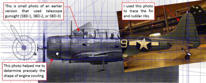
Then I used many other photos and sketched fragments of the other views to complete the side view details (Figure 4‑2, note the multiple guide lines):

Note the large B/W photo that I used to verify the shape of the propeller hub and engine cowling. I could not compare it with other areas — the cockpit canopy, for example — because its perspective (barrel) distortion was too intense.
However, when the barrel distortion is moderate, we can revert it! See for example this side photo of another Dauntless version: the SBD-3 (Figure 4‑3):

First I identified the undeformed fragment of the fuselage (in this case — around the firewall and the windscreen) then fitted this part of the photo into the drawing. Then, comparing the lengths of this photo and the side view, I concluded that it has a moderate barrel distortion. From the history of this design I know that the SBD-3 and SBD-5 had different engine cowlings. The other parts of their airframes had the same shape. This means that I could use the existing SBD-5 drawing from the firewall to the fin as the reference for the unwrapping process of this SBD-3. Then I unwrapped this photo using the GIMP. (Speaking more precisely – its “Lens Distortion” image filter. You can find all the details of this process in this book).

Note that this operation “flattens” only the airplane contour that lies on the symmetry plane of the fuselage. All protruding elements, like wing and horizontal tailplane remain deformed. But it’s OK, I need this just this contour. While drawing, I will compensate the small remaining deformation of the bulkhead lines. (For example, the leading edge of the NACA cowling from this photo should be a straight line, but it is a very flat ellipse).
Of course, it is always better to prepare more than one of such “flattened” pictures (Figure 4‑5), to minimize inevitable errors:

NOTE: these two SBD-3 photos depict training aircraft, without the telescope sight. Such a gunsight was protruding through the windscreen in the combat airplanes.
On both SBD-3 photos you can see that the engine cowling is somewhat shorter than in the SBD-5. In fact, in the specifications you can find that these versions had different overall length:
- SBD-5: 33’ 1/8”;
- SBD-3: 32’ 8 ” (in some sources I also saw 32’ 8 4/5”);
However, on the scale plans authors attribute this difference to the longer propeller hub of the SBD-5 (It used different propeller: Hamilton standard hydromatic). Others did not bother about the different lengths of the SBD variants, and draw the profiles of all Dauntless versions alike.
Following the findings on the unwrapped photos I analyzed many other archival pictures. Below you can see the conclusion (Figure 4-6):

It seems that in the SBD-5 the engine, together with the NACA cowling, was moved slightly forward. All other bulkheads remain in the same places. This modification shifted forward the center of gravity. I suppose that this correction improved some handling characteristics that changed after the doubling of the rear guns. (The second gun in the rear was introduced in 1942 to the SBD-3 as the “field” modification. It shifted the cg backward).
In the next post I will finish the side view matter, delivering you the complete side views of the SBD-3, SBD-2 and SBD-1 variants. I will also write about other non-existent length difference, which you can find in the books about the SBD Dauntless.
Hi !, i wonder how do you determine the angle at wich the airplane is when using reference pictures ? Thanks, Rodrigo
LikeLike
Well, it comes from the initial analysis of the photo – you can see it in this post:
https://airplanes3d.wordpress.com/2015/05/17/the-photos-reveal-the-truth/ , Figure 2-2.
I used some known facts about the geometry of this particular aircraft type. The pitch angle: in such a side view – you can easily trace it, along an element that had a horizontal contour (in this case: the bottom edge of the cockpit canopy). This photo has minimal barrel distortion (it was taken using telescopic lens), so the yaw angle along its length is almost uniform. (I determined it along the trailing edge of the center wing section – it was perpendicular to the fuselage centerline). Finally the roll angle: as in the case of the pitch, you can determine it using any of the known horizontal elements. (In the Dauntless it was the leading and trailing edges of the horizontal tailplane, as well as the trailing edge of the center section of the wing)
LikeLike