In June 2019 I followed C. West suggestion and ordered a set of Douglas SBD original technical documentation from U.S. National Air and Space Museum. Technically these blueprints are stored on several microfilm rolls. In that time all what I knew about this package (NASM id: “Mcfilm-000000408”) was the information printed on the order form:

As you can see, this set has no index, which I could order earlier to examine its contents. When I finally received these microfilms in November 2019, I also discovered the meaning of enigmatic “(roll C” in the item description: it was truncated phrase “(roll C missing)”!
Well, this set was incomplete, but anyway I ordered its high-resolution scans from a local company that provides professional microfilm scanning services to museums. In January I received these data (4700 high-res, grayscale images in LZW-packed TIFF format – in total, about 300 GB). Finally I was able to scroll these blueprints. Frankly speaking, I was afraid that the most important drawings were lost with the missing roll C. Fortunately, during the initial review I noticed many detailed assembly blueprints among the scanned images. I even found a complete inboard profile of the SBD-5:
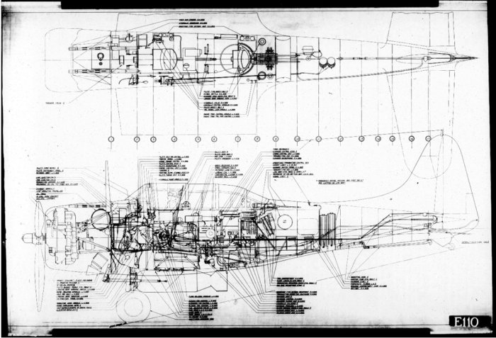
Here you can download the high-resolution version of this inboard profile (about 70MB).
The scanning company (Digital-Center, located near Poznan) did its job well, adapting the scanner resolution to the size of the depicted drawings. Scans of frames that contain large assemblies are usually 11 296 px wide and 7 874px high, which ensures that even the smallest references are readable. For example – see these four subsequent frames of the fuselage assembly drawing: 1, 2, 3, 4 (beware: size of each of these linked images is about 70MB).
There are even larger images in this result set: the biggest one is about 20 000px wide. The smaller drawings of various details are scanned at 7 672×5 682px.
Conclusions from the first review of this microfilm set are as follows:
- Roll A: blueprints of various small elements. Many of them (various angles, straps, bolts, pins, etc.) are standard Douglas parts, shared between many aircraft types. (As the angle from Figure 107‑5 – it was traced in 1936, before the SBD appeared on the designer desks);
- Roll B: blueprints of various SBD details – special bolts, pins, screws, various brackets, supports, forged parts, some minor assemblies (for example – arresting hook);
- Roll C: missing
- Roll D: assembly drawings
- Roll E: more detailed assemblies, some larger details
- Roll F: remaining elements (this is the shortest roll)
- Roll XA, XB: updated drawings, published a few months later. Most of the drawings are duplicates of those depicted in rolls A-F, but can differ in minor details. However, some of these drawings are new – most probably they are updates of the drawings from the missing roll C;
These blueprints describe SBD-4 and SBD-5 (which is OK – the SBD-4 is similar to SBD-3, and SBD-2, while SBD-5 is nearly identical to SBD-6). It seems that rolls A-F were made from September to October 1943, while their updates – rolls XA, XB – in January 1944. Because of the missing roll C, this documentation is not complete. In general I could not find the fuselage ordinates (I only found the wing ordinates). My first impression is that the missing roll C contains most drawings of wing ribs and at least half of the fuselage bulkheads. Fortunately, there are drawings of the tail bulkheads and the firewall on the other rolls.
For my project I need to organize these blueprints into a tree-like structure, with the largest assemblies in the root (as described in this post). However, after this initial review I could not determine the rules of the drawing numbering system used by Douglas. (I wanted to use them for quick grouping all parts belonging to the same subassembly). It could happen that in this Douglas factory the drawing numbers were assigned sequentially, just as the subsequent blueprints were ordered! It also seems that some of these drawings use original Northrop numbers, dating from the SBD predecessor: the BT-1 dive bomber.
To organize this documentation I have to start from the general assembly drawing and then step down to its subassemblies. For this purpose I need an index of these blueprints. Recreating such a thing is a monotonous task that will take some time, but I cannot see better option to fully explore contents of these microfilms. What’s more, I think that once such a list is created, it can be also useful for the others. While NASM forbids publishing technical drawings from their microfilms by any means (except so-called “fair use”, which I am stretching a little in this article), I still can publish such an index. Of course, I will also donate its copy to NASM. I hope that in this way the eventual future buyers of these SBD/A-24 microfilms will benefit from my work.
First obstacle in creating such a drawing list is quite unusual: while most manufactures traced the digits of drawing numbers in ink, as the all remaining drawing lines, Douglas stamped them in the title block. The ink often spilled over the edges of the stamped digits, and now it is hard to read them from the microfilms photos. For example – look at the title block of this sample drawing:

When I altered the gray shades of this drawing, I was able to identify the first four digits (5063):
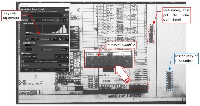
Fortunately, after this adjustment I discovered that they also stamped (most probably) the same number on the right margin. So here it is: 5063493. (You can also find a mirror image of this number on the right below: most probably it was stamped on the other side of this drawing). Of course, sometimes even these additional stamps on the margins are hardly readable: I frequently wondered whether a particular “splash” in place of a digit represents “4” or “1”. In other cases it was difficult to tell if there is a “3” or “8”, or “5”, or even “0”. Some help came from the observation that the numbers of these microfilm drawings are always in ascending sequence. Thus, if the unreadable digit in the drawing number “519456x” can be “3”, “5”, or “8”, but the previous drawing is “5194560”, and the next drawing is “5194565”, then this last digit must be “3” (giving drawing no: “5194563”).
Still there are cases in which I was unable to decipher the drawing number even after adjusting the grayscale, and there was a wide gap between the previous and the next drawing number:
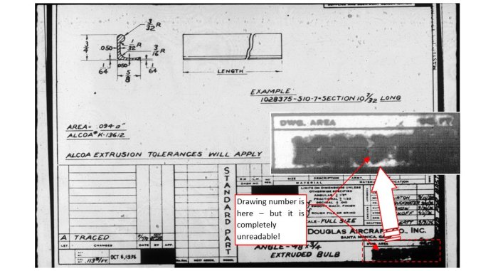
The standard parts, like the one depicted in Figure 107‑5, often occur in several variants (you could cut the depicted standard angle in a variety of lengths). In such a cases Douglas placed in the drawing an example of the full part number:

The prefix of this part number is the drawing number!
In case of unreadable dedicated part/assembly drawing numbers, Ester A. from AirCorps Library suggested the “last resort”, indirect method. Usually the blueprint of a non-standard part contains a table named “NEXT ASSEMBLY” on the side of the main title block. It provides drawing numbers of the assemblies that use this part:

In the case from Figure 107‑7 this is a single assembly drawing: 3063922, which was used in the SBD-1, -2, and -3 models. Using this drawing number I found the corresponding blueprint:
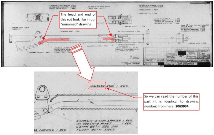
Examining this assembly drawing, I found the sought detail and read its number. Of course, this method requires searchable list of the available drawing numbers, from which I would read that drawing 3063922 is in roll B, frame 1014. That’s why in the first step I needed to create the drawing index.
It took me about 100 hours of work, but here it is:
Click here to download the index (*.xlsx file, 303kB).
Frankly speaking, for my purposes I do not need the details from roll A, which took about 25% of the total work time. But I decided to index all the rolls, just to provide a complete list for eventual other users.
Below you can see how this list looks like:
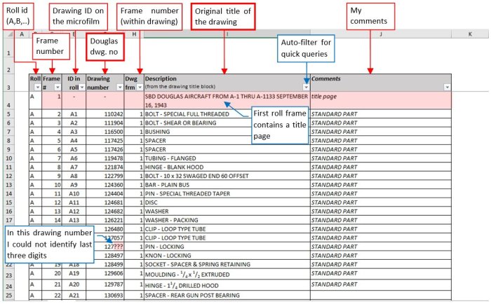
For each microfilm frame I note in this table not only the drawing number, but also the name copied interim from the drawing title block. (I preserved in these texts original caps and the grammar errors – for example: “PILOTS CHAIR”). Eventual unreadable digits in drawing numbers are marked as “?”, and unreadable text fragments as “<…>” (as in Figure 107‑12).
It seems that in Douglas numbering system drawing numbers of standard parts should have “S-“ prefixes. However, I found that these prefixes were often missing, or even manually written in drawings of certain parts that do not seem to be standard. Thus I decided to skip “S-“ prefixes in the numbers placed in this index, because they could be misleading and make the eventual searches more difficult. Instead I marked each drawing of a standard part in the Comments column, basing on the presence of the “STANDARD PART” statement in its title block.
When a single drawing spans over two or more subsequent microfilm frames, I described it in the index table in following way:
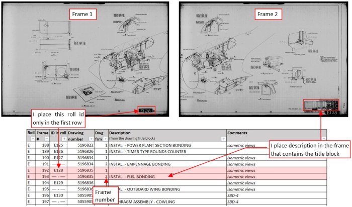
Each line in the table represents single microfilm frame, thus drawing 5196835 is described by two subsequent lines, which differ by the drawing frame number in the Partial frame column (1, 2). In the first of these lines I placed the roll id of this drawing (“E128”). I did this just in case, because I do not think that I will use these ids. I placed drawing description (title) in the line that corresponds to the frame containing its title block. In this way the table contents is more readable. (You can instantly recognize for each drawing where it starts and ends).
In this list you can use Excel filtering feature, searching for drawings that contain certain phrase. When you click the auto-filter button in the right corner of Description column, and search for “BONDING” phrase, you will get following result:
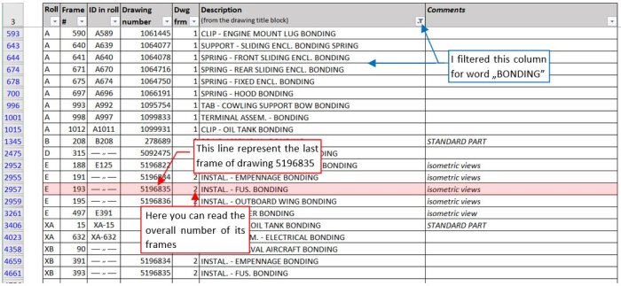
If you did this search because you wanted to find the drawing of the fuselage bonding, in the result set you will see the last line of drawing 5196835 (the one that contains the description from its title block). You can read the roll symbol and the frame number from Roll and Frame # columns (roll: E, frame: 193). From the Dwg frm column you will learn that this is frame 2/2, thus you will also know that previous frame (192) from roll E contains the first part of this drawing.
Finally, Figure 107‑12 shows one of the most complex examples of a multi-part assembly drawing:

A very long drawing 5094762 (E138) was originally traced in two parts (1/2, 2/2). Each of these parts spans over 3 frames and has its own title block, thus I placed their labels in the corresponding index lines. What’s more, this assembly is accompanied by additional BOM tables, depicted in the subsequent microfilm frames (6, 7, 8).

Hello,
The High Res downloadable drawing is only a part (Tale part) of the featured drawing, so not worthwhile to download, pity !!
LikeLike
OK, now I see, this is just an explanation of how to order the drawings, my apologies for my former comment ! But still this all is very interesting, although I am more interested in ships !!
LikeLike
It’s my small mistake: my intention was to provide the inboard profile as in the Figure107-02. I just made an error in linking files! Now I updated the link, you can download it. Also note that in the paragraph below under links “1,2,3,4” I am providing four parts of the detailed fuselage drawing – as an illustration how detailed are these blueprints.
LikeLike
Thanks a lot Witold, appreciate it !!
LikeLike
I am always impressed by these High Resolution drawings, even if they are airplane drawings 😉
As I told before I am into High Res ship drawings and what I am doing right now is Re-Draw original drawings. The first I did with Photoshop, but recently I switched to EazyDraw, a vector program, especially designed for Mac computers !
LikeLike
WE LOVE YOU! Great good quality.
LikeLike