In this post I will finish my model of the R-1820-52 “Cyclone”. (This is the continuation of the subproject that I started reporting in the previous post). Figure 92‑1 shows the oil sump, used in this engine:

Oil sump shape vary even within the same G100 family: I observed different proportions of the front “barrel” and its forward pipe in the early and the later of these “Cyclone” models. This particular oil sump (Figure 92‑1a) was used in the later G100s engines, like the R-1820-52. Apart from the forward pipe, it was also attached to the front crankcase via a “chin” (Figure 92‑1c).
To avoid eventual confusion, I would like to clarify the multiple naming conventions of the same engine: In the further text I will also use the internal Wright name for this “Cyclone” family: R-1820G100, or simply “G100”. The R-1820-52 engine is one of its members. (A month ago I finished a model of one of the later “Cyclone” versions: R-1820-60, which represents another, the “G200” family). I explained details of these nomenclature in this post.
While I have a few photos of the forward part of the oil sump, I have not any evidence of the shape of its rear part. (Because of the different shape of the intake pipes, I do not think that it forms the “Y-shaped” fork, like in the G200 series). All what I had found is a single, poor quality photo of the damaged engine recovered from Lake Michigan (Figure 92‑2a):

There is “something” at the bottom of this crankcase: it has a trapezoidal shape and (probably) two inner (oil?) ducts inside. I decided that this is the rear base of the oil sump (Figure 92‑2b). It is quite thin (no more than 1”), fitted between the crankcase main section (cylinder bases) and the intake pipe (Figure 92‑2c).
As you can see, I have made lot of various assumptions about the rear part of this oil sump. Well, in every model you can always find some elements that have such a “hypothetical shape”. However, this is the last resort, when all my photo queries brought nothing.
As I described in the previous post, the R-1820G100 and R-1820G series used the same deflectors. Thus I recreated the upper deflector (the “rectangular” version) using photos of a restored R-1820G engine, from the F3F-2 (Figure 92‑3):

I recreated the sheet metal frame and the flexible (rubber?) tip (Figure 92‑3a, c). The photos from the recovered SBD-1 show, that there were some variations in the shape of the deflector rear part, around the spark plug. In the R-1820-32 from the SBD-1 I can see a kind of additional cut-out for the ignition cable, which is missing in this F3F-2. (F3F-2 had a different ignition harness – compare the deflectors in Figure 92‑3b and Figure 92‑3d).
The top cylinder in the SBD-2…-4 had the elastic tip removed. (Because of the fitting the engine to the “Duntless” NACA cowling – I will show it later n this post). Thus I defined this deflector as another group instance, named F.G11.Deflector. (In the R-1820-60 model the top deflector is the part of the cylinder group).
In similar way I modeled the side deflector (Figure 92‑4):

This deflector also has a flexible tip. As you can see, I skipped here some details (Figure 92‑4a) that do not appear on every object instance. Note the characteristic “bat-like” fitting in the front of this deflector (Figure 92‑4b). (The R-1820-60 deflectors had different fittings).
The last remaining details are the spark plug harness and the oil scavenge pipe (Figure 92‑5):
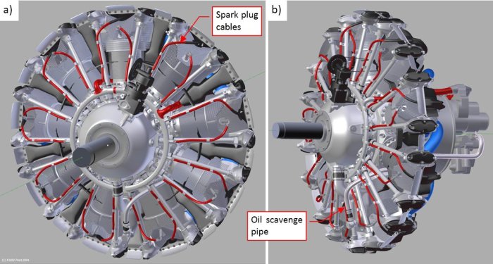
As in the previous case, I am leaving the invisible, rear part of this engine in the simplified, “block” form.
Finally, I imported the NACA cowling from the main model and placed the engine inside. Fortunately, it fits very well (Figure 92‑6a):

In the R-1820-52 (and -32 in the SBD-2) the deflector on the cylinder 1 top was mounted without the flexible tip, to fit below the air intake duct of the upper cowling (Figure 92‑6b). Both of the cylinder 1 side deflectors also had their flexible tips removed, to fit below the gun troughs.
In the R-1820-60 and -66 (used in the SBD-5 and 6) the cylinder 1 featured the full top deflector. (It was possible, because, as I explained in this post, SBD-5 and -6 had two filtered air intakes, used for takeoffs. For the higher airspeeds there was enough “fresh” air for the air intake hidden behind the cylinder row). The R-1820-60 had different fittings on the cylinder 1 side deflectors that fit the gun troughs (Figure 92‑6c).
The R-1820-52 is now complete, for the assumed level of details. You can download the model presented in this post from this source *.blend file. I think that it can be also useful for the models of the other aircraft that featured the geared R-1820G or R-1820G100 engines. (Like Brewster “Buffalo”, DC-2 and some versions of the DC-3, or Curtiss “Hawk” 75). The exhaust stacks are not included, because this is an aircraft-specific detail (as the eventual air intake filters in the SBD-5 and SBD-6). I will recreate these details in the next post, for both of my ‘Cyclone” models.

Your use of the term “SLUMP” is Incorrect. The Proper term is “SUMP”. Just Sayin ! – Johnman
LikeLiked by 1 person
Thank you for this correction!
LikeLike
the only R1820s with the external scavenge pipe were the -97 and -99. Some -65s had the pipe retro fitted and the i.d.plate overstamped -97.
LikeLike
I can see this pipe in all the R-1820-52s, used in the SBD-3 and -4.
LikeLike
Is this ready for 3D print? I’m interested in purchasing.
LikeLike
Unfortunately, none of my models is 3D-print ready. (I am building them for computer visualizations). However, you can adapt it for your purposes. (This 3D model is on the CC license). To get the source (Blender) file, use the link that I placed in the last paragraph of this post.
LikeLike