Following the conclusion from my previous post, I have to recreate yet another “Cyclone” version: the R-1820-52, used in the SBD-3 and SBD-4. Fortunately, the R-1820-32, used in the SBD-1 and SBD-2, seems to be identical (at least – as viewed from the front), thus I do not need to recreate this “Cyclone” variant. I will describe the modeling process of the R-1820-52 in the “fast forward” mode, compressing the whole thing to two posts: this and the next one.
Initially I identified just two differences: the shape of the front crankcase section and the different ignition harness. I assumed that I will be able to reuse most of the R-1820-60 components. I had discovered most of the issues described in my previous post while working on this R-1820-52 version. In fact, it occurs that such an attempt to create a 3D model of such an engine is like an scientific experiment: it verifies the initial hypothesis and reveals the new facts that otherwise would be overlooked.
I started by renaming in the source Blender file the scene that contains the previously finished engine as “R-1820-60” (the “military” symbol of an engine belonging to the “Cyclone” G200 family). Then I created a new scene, named “R-1820-52” (the G100 family). This is my new “working place”. I copied there (precisely speaking: “linked”) some of the “R-1820-60” parts that were common for the G100 and G200 family. In this “*-52” version I followed the same “building path” which I used for the previous one. So I began with the crankcase and the basic cylinder elements (Figure 91‑1):

I assumed that all the key dimensions and bases are identical in both versions, just the details are different. This assumption allowed me to determine the shape of the forged, “angular” main section of the G100 engine crankcase using just a few photos of its fragment (as in Figure 91‑1a). (This element is quite obscured on all the photos that I had). The nine side faces of this section had to fit the corresponding cylinder bases. The adjacent, oblique faces between the cylinders had to fit the space between cylinder bases and the front / rear plane of this central crankcase section. However, while fitting the crankcase and the cylinders, I also had found that the 16-bolt cylinder base used in the R-1820-52 had a longer straight side segment (Figure 91‑1b) than the 20-bolt base used in the R-1820-60. Because most of the cylinder parts were assigned to the E.100.Cylinder Base object (the “bare” cylinder), I decided to split it into the upper and lower part. The mesh of the upper part is assigned to this original E.100.Cylinder Base object, and used in both engine versions (Blender scenes). Each of these engines has its own lower part of the cylinder (marked in red in Figure 91‑1b). The 20-bolt version is used in the “R-1820-60” scene and named G.100.Cylinder Base, while the 16-bolt version is used in the R-1820-52 scene and named F.100.Cylinder Base.
To keep an order in this two-scene setup, I decided that the parts used in both versions (scenes) retained the “E” prefix in their names – for example “E.015.Disc”. The parts specific to the “-60” engine received the “G” prefix, while the parts of the “-52” engine received the “F” prefix.
The crankcase front section in the R-1820-52 had smaller diameter than in the R-1820-60, and different side silhouette. Thus I had to model this fragment anew. I split it into 9 identical segments, as I did in the R-1820-60. However, after some measurements, I decided that the disc that closes this crankcase from the front is identical in both versions (Figure 91‑1b). To avoid eventual “orphaned” objects in my further work, I used this disc the root object in the “parent-child” hierarchy of both models.
In Figure 91‑1b) you can also see the initial versions of the pushrod bases, which I placed around the front crankcase section. They had characteristic “diamond” shapes. I recreated the “pattern” of these pushrod bases around the crankcase. This work led me to another small discovery: the G100s and the earlier “Cyclone” versions used different valve pushrod arrangement than in the G200s (Figure 91‑2):

Compare the “a” and “b” distances in Figure 91‑2a) and Figure 91‑2b). As you can see, there is wider space between the intake and exhaust valve pushrod (the “b” distance) in the earlier “Cyclone” G100 series (incudes the R-1820-52) than in the later G200 (includes the R-1820-60) series. The reverse proportion occurs between the pushrods of the adjacent cylinders (the “a” distance in Figure 91‑2). It seems that the pushrods in these earlier “Cyclones” were set along the radial directions, while in the later (G200) models they were set at a different angle.
There is also another difference: Wright engineers reversed in the G200s the order of the pushrod cams. In the G100s and earlier engines the base of the intake valve pushrod was shifted forward (Figure 91‑2c). In the G200s they set the exhaust valve pushrod first (Figure 91‑2d).
To match the rear rim of the front crankcase with the photos, I prepared its simplified, “block” version (Figure 91‑3a):

This “block” version is built of several simple elements, like the pushrod bases, the rear, flat elements, and so on. Once their shape matched the reference pictures, I joined these elements into the single, more complex object using temporary Boolean (Union) modifiers. Finally I joined it with the basic front crankcase segment (Figure 91‑3b). I also rounded the new intersection edges with a multi-segment Bevel (Weight) modifier.
In the G100s (incl. R-1820-52) and earlier “Cyclone” models the propeller governor was mounted at an oblique angle on a quite complex “shelf” extending from the crankcase (Figure 91‑4):
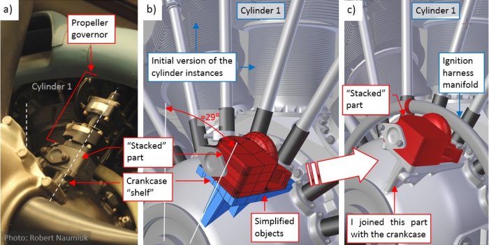
I applied here the same “approximation first” method, using intermediate simplified parts (Figure 91‑4b). (As you probably observed, it became my usual approach to such complexities like this one). After the “fitting” phase I joined the bottom part of this “shelf” with the crankcase, and rounded the resulting edges (Figure 91‑4c). On top of the “shelf” there was an additional, “stacked” part (I think that it was a kind of a cover). In the pictures above I marked it in red. In the final version I left it as a separate part, attached to the crankcase by the “parent” relation.
In the background of Figure 91‑4 you can also see the first versions of the cylinder instances (I will modify them in the next steps), and the ignition harness manifold. (I preferred to fit it on this early stage of this the model, to avoid unwanted surprises later).
When the “shelf” was ready, I put the propeller governor in place (Figure 91‑5):

I copied this governor from the R-1820-60 scene, then modified it a little (rotating the head with actuator wheel by 180⁰). Unlike in the R-1820-60, this object is set in the position parallel to the engine centerline. Looking from the front, it is mounted in an oblique position just to pass the control cable in the gap between Cylinder 1 and Cylinder 2. However, looking along this cable, I stumbled upon a new problem: it collided with the intake pipe! (Figure 91‑5b).
I quickly found a photo that explained me this puzzle (Figure 91‑6a):

As you can see in the picture above, the intake pipes in the G100s models formed large arcs, leaving the gap between the Cylinder 1 and Cylinder 2 open for the control cable. This means that I have to modify these pipes in my R-1820-52 model.
Thinking about the altered angle of the valve pushrods (see Figure 91‑2) I checked the clearance between them and the cylinder head. In the R-1820-60 they were placed in deep troughs, “cut out” in the cylinder fins. I was surprised by the photos showing that in the R-1820-52 these pushrods would not collide with the cylinder head, even if this head did not have the minimal, shallow troughs. I studied this cylinder head closer: the spark plug hollows also seemed to be shallower, and the upper contour of the fins (as viewed from the front) was lower in its middle section. I started to compare proportions of these cylinders. Finally I decided that the fins in the heads of the R-1820G and R-1820G100 series were shorter than in the R-1820G200 (i.e. in my R-1820-60). I estimated that the G100s cylinder heads had 10% smaller diameter than the G200s heads. (It means that cooling area of the G200 cylinders was about 30% larger than the cylinders used in the G100s. It matches the differences in their power).
Well, now I had to apply these findings to my model (Figure 91‑7):

Fortunately, the “pattern” of the cylinder fins seems to be nearly identical in the G200s and G100s cylinder heads. (I have found just a single minor difference in their forward part). Thus all what I had to do was to prepare new, smaller “fin boundary surface” (Figure 91‑7a), then apply it using Boolean (Intersection) modifier to the same mesh of the fin planes. I could reshape the intake pipe by altering the shape of its control curve (used in the Deform Curve modifier of the intake pipe). You can see the results in Figure 91‑7b).
Figure 91‑8 shows the actual state of the R-1820-52 model:

Cylinders 2-9 are instances of the object group named F.G05.Cylinder. The source of this group are the components of the Cylinder 1. When I modify the source Cylinder 1, Blender immediately updates the remaining eight cylinders. Components of Cylinder 1 lie on two layers: 3 and 13, while the group instances belong to the single layer: 3. I have found such an arrangement most useful for the constant work on the cylinder details – I often did it on layer 13. Note that I also modified the bases of the intake pipes (I had a single, poor quality photo of this area). In general, it seems that the rear crankcase section of the G200s that I roughly recreated in the R-1820-60 is similar in the R-1820-52. The same applies to the magnetos and oil pump.
This engine still lacks the cylinder deflectors, oil sump, and spark plug cables. In the next post I will finish all these details and fit it into the NACA cowling.
You can download the model presented in this post (as in Figure 91‑8) from this source *.blend file.

Hi there, i found your site again after remember the addon to make section cuts. I wanted to see this model and now wonder why you model on such huge scale?
LikeLike
Thank you for visiting this blog! For this model I assumed that 1 Blender unit = 1 inch, because all the detailed dimensions in the original Dauntless blueprints are in inches (even the wing span). It is just more convinient
LikeLike