In this post I will recreate the main and the front sections of the crankcase, and the cylinder basic shape. Let’s start this model by forming the middle section of the crankcase (Figure 84‑1):
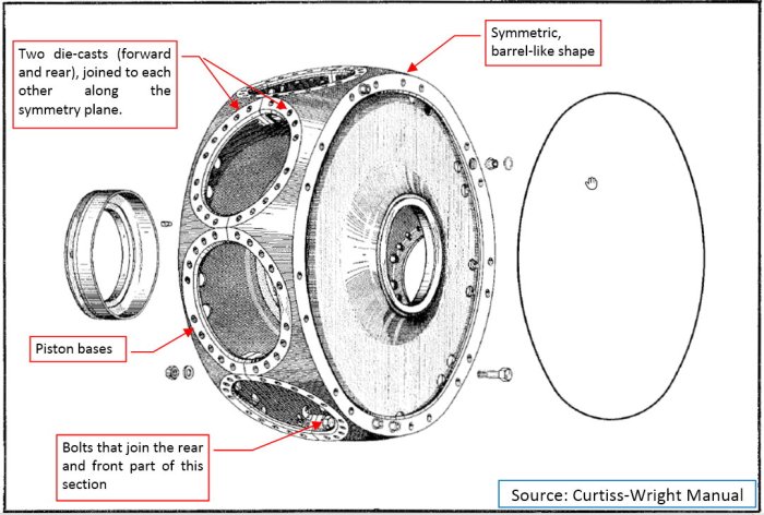
This section is always obscured by the cylinders, so you cannot see it clearly on any photo. That’s why I used here the original drawing from the manual. Generally, this barrel-like shape contains nine cylinder bases. It is formed by two steel castings, bolted to each other. (These bolts are hidden inside the crankcase, between the cylinder openings).
It is always a good idea to start with a simplified model. It allows us to check all constrains of the geometry that are not obvious at the first glance from the reference drawings. In this case started by forming a symmetric half of the crankcase (Figure 84‑2):
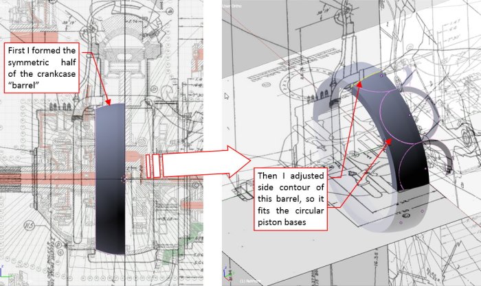
This is a simple barrel, smoothed with a Subdivision Surface modifier. Then I placed the flat piston bases along the circumference of this crankcase. I quickly realized that the side contour of this barrel depends entirely on the size and shape of these piston bases. After a few quick adjustments of the control edge loops, the barrel surface “touched” the outer edges of the piston bases along their whole length (as in Figure 84‑2).
Note that these piston bases are so tightly packed around the crankcase, that they nearly join each other along a short, straight edge (Figure 84‑3):
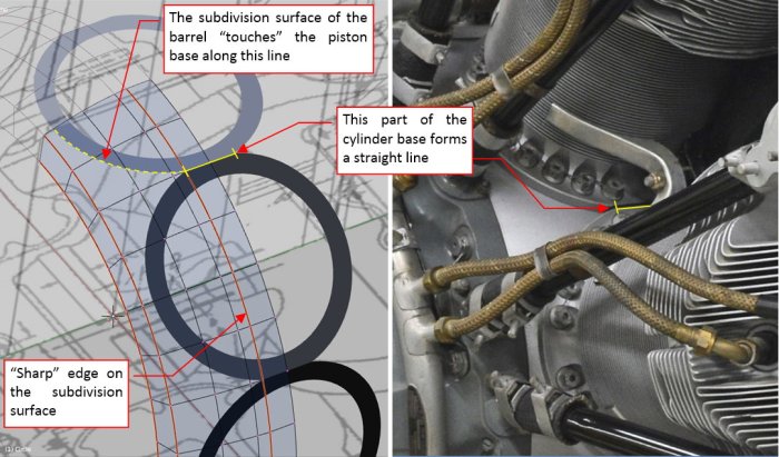
This means, that the crankcase barrel contains a cylindrical strip in the middle, which matches this straight edges on the piston bases. In fact, the sharp corners of these edges forced similar sharp edge on the barrel side contour.
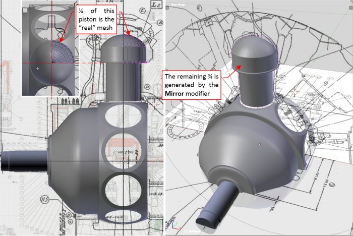
When the general shape of the crankcase barrel looked right, it was time to create the final mesh. I decided that I will not use the dynamic effects of the subdivision surfaces for such a complex objects as the engine parts. (Because I want to keep the polygon count of this engine model below 1 million). Thus I “fixed” this subdivision effect, converting it into the normal faces (by “applying” the modifier). Then I took take the advantage of the “repeatability” of this shape. I deleted all the faces of the original “barrel”, leaving just the 20⁰ “slice” (Figure 84‑4a):
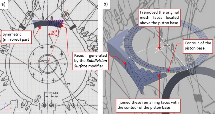
The opposite 20⁰ of this “slice” is generated by the Mirror modifier. Then I made further modification to this mesh, removing all the faces from above the piston base (Figure 84‑4b). I also copied and inserted into this mesh a quarter of the piston base contour. Then I started to join this contour and the mesh around it with new faces. You can see the result in Figure 84‑5a):
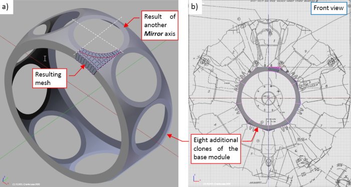
As you can see, I also recreated the rear part of this crankcase section, just adding another symmetry axis to its Mirror modifier. The whole body of this crankcase can be built from 9 clones of such an object (as you can see in Figure 84‑5b).
The shading of the crankcase faces is set as Smooth, except the faces around the piston base (which are marked as Flat).
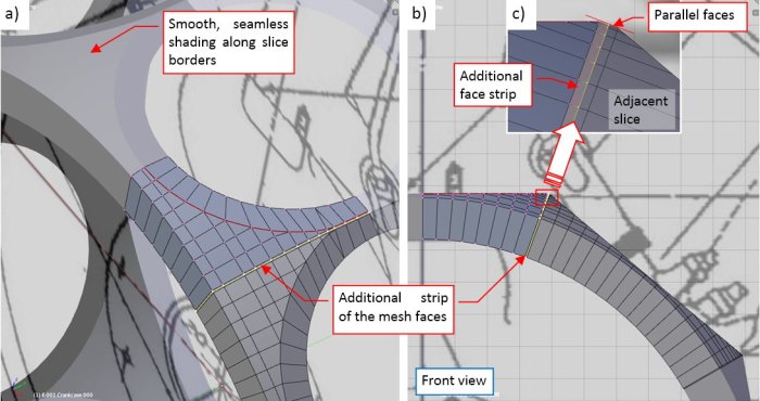
I would like to mention a little “trick”, which can be useful in many other cases. To obtain a seamless join between the crankcase “slices” (as in Figure 84‑6a), I added an additional, thin “strip” of the faces around the slice edge. These faces are parallel to the faces of similar strip in the adjacent slice (Figure 84‑6b, c):
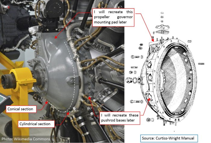
Once the middle section of the crankcase is ready, I started working on its front section. Generally speaking, this part looks like a combination of a cone and a cylinder, with many “protrusions” of additional details (Figure 84‑7):
Actually, I recreated the basic shape of this section. (I will recreate the remaining details later). I did it using the same workflow as in the case of the previous section. First, I made a simple, “conceptual” model of this part. It was smoothed using a Subdivision Surface modifier. When the shape seemed to be OK, I converted the result of this modifier into normal mesh faces. Then I removed all the unnecessary edge loops and created the basic 20⁰ “slice” of this section (Figure 84‑8):
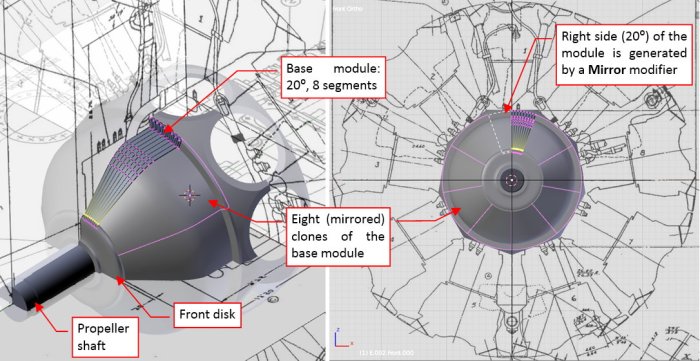
To obtain the smooth shading between slices, I also created the additional thin strips of parallel faces along their adjacent edges. The basic slice of this section was easier to form than the one from the middle section, because it did not contain any opening.
Just to make the front of the engine more complete, I created the front disk (in a classic way, no “slicing” here) and the propeller shaft.
Finally I started working on the cylinder. Because all cylinders of this engine are uniform, I will complete a single (the topmost) one. The complete cylinder will be an assembly of many objects. Then, when it is finished, I will clone it around the crankcase.
As the first object in this assembly I created the simple, basic cylinder (i.e. the cylinder and its head without the fins and rocker covers) (Figure 84‑9):
It will be the parent object of all further elements of the cylinder assembly. As in the case of the crankcase, it does not use any Subdivision Surface modifier, just the “fixed” mesh faces with the Shade Smooth option (and Mirror and Bevel modifiers).
You can check details of this model in the source *.blend file. In the next post I will model the rocker covers and the covers of the intake/exhaust valves. (In the R-1820 they are just fragments of a single-piece cylinder head).

Please kindly give us a step by step tutorial for us to be able to follow. As it is now it is hard to follow these instructions. As an example you say the crankcase is a barrel. But there is no mesh tool in blender which is a barrel. What mesh did you use to create the crankcase. Did you start with a circle mesh or what. Please elaborate a bit for us to be able to create this project. Thanks
LikeLike
Thank you for reading these posts. They are not intended as step-by-step tutorials, rather a kind of reports for fellow 3D modelers. I assume here a certain experience level in the 3D modeling.
Yes, I created this barrel shape from a circle (extruding its subsequent sections).
If you are looking for a step-by-step tutorial on aircraft modeling (on the example of the P-40B, not a radial engine, but the basic techniques are the same), consider buying my book on this subject: http://airplanes3d.net/wm-000_e.xml
LikeLike
Please create a step by step tutorial on modeling a radial engine because modeling a radial engine is different from modeling a fuselage of an aircraft. Thank you.
LikeLike
Please we need a step by step tutorial on modeling the radial engine in a book form if possible. Thank you.
LikeLike
Did you ever made a step-by-step tutorial for such a quite complex assembly like this engine? It would take me about six to eight months!
I will not do it, because I am engaged in other projects.
LikeLike