The Dauntless had fixed tail wheel of a typical design among the carrier-based aircraft. The tail wheel assembly consisted a fork connected to two solid-made beams, which movement was countered by a shock strut. The beams and the shock strut were attached to the last bulkhead of the fuselage (Figure 82‑1):
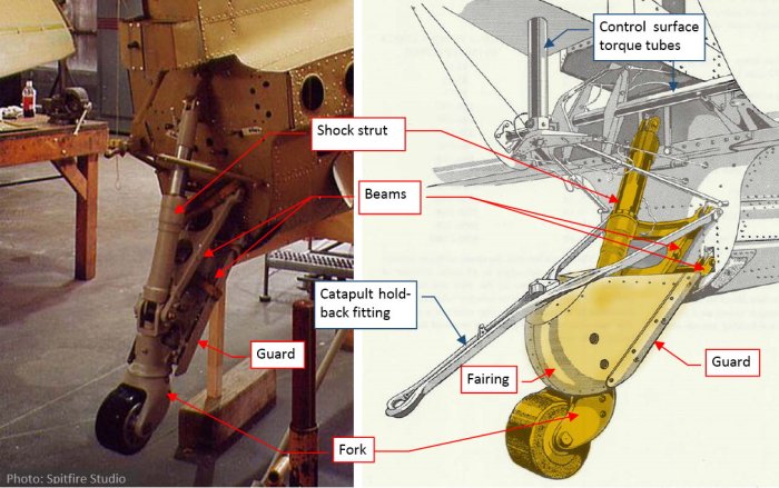
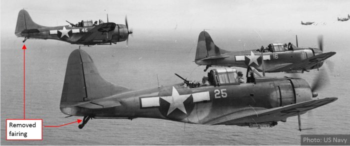
The bottom part of this assembly was covered by a guard and a fairing. Both of these elements were attached to the lower beam. The archival photos reveal that the bulky fairing was often removed (Figure 82‑2):
There were two tail wheel versions: the smaller, solid-rubber wheel for the carrier-based aircraft (as in Figure 82‑1, Figure 82‑2), and the larger, pneumatic wheel for the ground-based aircraft. As you can see on the example of a SBD-1 (below), they could be replaced in a workshop:
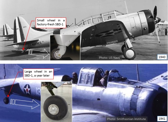
Figure 82‑3 shows two SBD-1s, which were exclusively used by USMC squadrons in the continental United States. All of these 57 aircraft were built in 1940. As you can see in the photo above, they were originally delivered with small, solid tires. However, in the photo below, taken a year later, one of these SBD-1s has the large, pneumatic tail wheel. It seems that Douglas delivered these large wheels to the Navy / USMC as an optional kit, which could be mounted when needed.
The smooth tip of the tail was mounted to the last bulkhead as a light, easily detachable tail cone. It covered the tail wheel shock strut, as well as the rudder and elevator control mechanism. There was a large opening in the bottom of the tail cone. For certain sunlight directions (for example, in a dive) you could “look inside” the fuselage (Figure 82‑4):
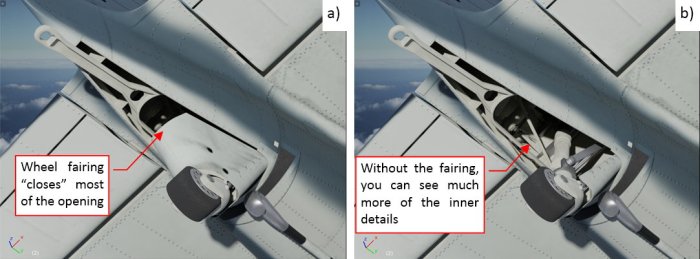
As you can see in the figure on the left, the tail wheel fairing effectively closed most of this view (Figure 82‑4a), so that you could see just the catapult holdback fitting, two ribs and their stringers. However, when you remove this fairing, you can see many details inside (Figure 82‑4b). Of course, they are not visible on most of the photos. These details are hidden in the pictures taken on the ground. In most of the in-flight photos this opening seems to be too small to reveal the interior details. However, thinking about the future scenes of diving bombers, I decided to recreate at least the key internal elements of this tail cone.
While the tail wheel in the SBD does not retract, it follows the shock strut compression. Thus recreation of this assembly requires some initial adjustments of these moving parts. (For example: I had to make sure that the wheel leg will fit into the tail cone). I am shortly describing this process below (Figure 82‑5):
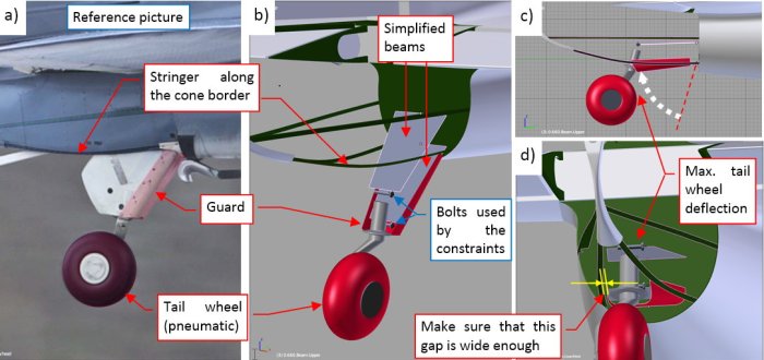
I started with the tire, its fork and the guard, which are present on my reference photo (Figure 82‑5a). I also added the stringers along the border of the opening in the tail cone. Then I placed the simplified shapes of the tail wheel beams. At the beginning I did not know their proper width, thus their initial mesh was a simple, four-vertex trapeze, ready for eventual adjustments. In Figure 82‑5b) you can see also a bolt at the end of each beam. They were important parts of this “virtual mechanism”. No armature was needed in this case. I decided that the lower beam will be animated by the handle movement. Thus I forced the upper beam to follow its rotation using a Copy Rotation constraint. Each of these two bolts is attached (by parent relation) to the corresponding beam. The tail wheel fork is attached (by parent relation) to the lower bolt. Simultaneously this bolt rotates, tracking the center of the upper bolt (using a Locked Track constraint). Thus, when I rotate the lower beam, it rotates the whole assembly (as in Figure 82‑5c). Then I adjusted the width of the guard and the beams so that in the fully deflected position it fits the opening in the tail cone (Figure 82‑5d).
Once the overall size of the beams was determined, I recreated their shapes, as well as the catapult hold back fitting, shock strut, and the tail wheel fairing (Figure 82‑6):
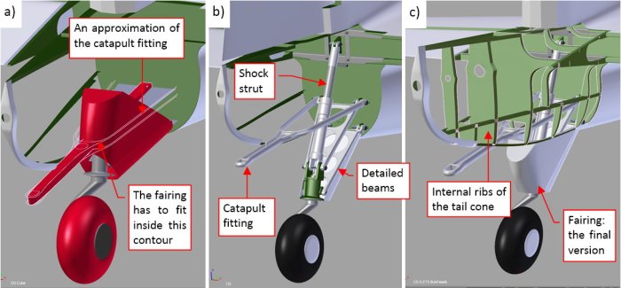
The catapult fitting was attached to the ribs of the tail cone. Its side arms were fitted between the tail wheel fairing and the stringers running around the border in the tail cone opening. As you can see in Figure 82‑6a), I started with the conceptual lines of this part. Then I used them to form the final “Y” – shaped fitting (Figure 82‑6b). Using similar methods I recreated the beam details. (I could do safely, because they were already fitted to the tail cone, and I do not expect any further changes in their shape). Finally I also added the internal ribs of the cone (Figure 82‑6c).
In the next step I recreated the rudder/elevator torque tubes and their fittings (Figure 82‑7):
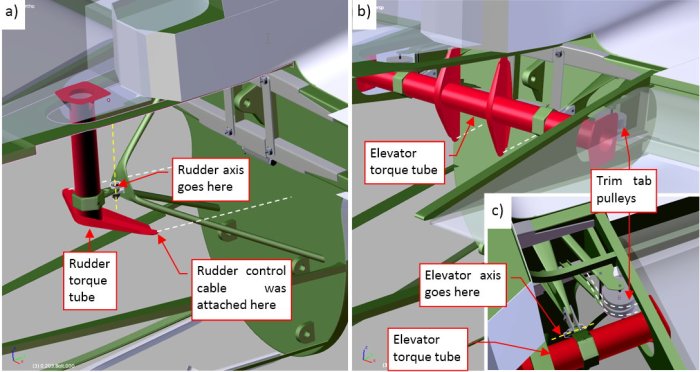
Figure 82‑7a) shows the rudder torque tube. It was mounted on a tripod. Note, that the rudder rotation axis lies in the front of this tube. (It rotated around the bolt that joined the torque tube with the tripod). For this level of detail I did not recreate the control cables. (Perhaps I will do it in the future). I also formed the elevator torque tube (Figure 82‑7b). Its rotation axis also lies in the front of the tube. According the maintenance manual, there were also two pulleys for the elevator trim tab cables (Figure 82‑7c). Unfortunately, I do not have any precise photo of this detail. I recreated their brackets using two rough sketches from the maintenance manual, but about 50% of their size and shape is just my guess. If any of you have a photo of the details from Figure 82‑7c) (for example – from a restored SBD), let me know. I would appreciate any of such pictures.
Figure 82‑8 shows all of the tail cone internal details that I have recreated so far:
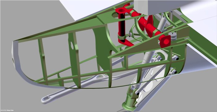
For the assumed level of details I simplified some small elements, like the trim tab pulleys. I also did not recreated other minor, less visible elements like control cables, electric cables, some additional fittings and bolts. I will recreate them later, when I decide to make cutaway pictures of this model.
To recreate the alternate, “solid” version of the tail wheel, I switched to another reference photo (Figure 82‑9):
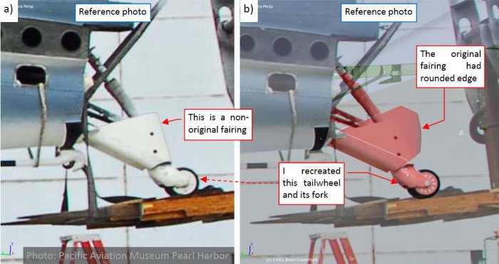
The SBD on this reference photo was restored for Pacific Aviation Museum Pearl Harbor. Although the restoration teams do their best to recreate their “birds”, sometimes you can find a non-original part on their aircraft. In this case it was the tail wheel fairing: it is smaller and simpler (Figure 82‑9a) than the original part (Figure 82‑9b). However, the rest of the tail wheel assembly seems to be original, thus I used this photo as the reference for the “carrier-deck” version of the tail wheel and its fork.
Finally I also added the tail hook (it was removed only from the A-24s, delivered to the Army). As you can see, it was accompanied by some minor details (Figure 82‑10):
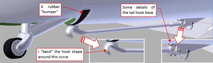
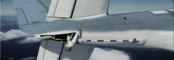
Figure 82‑11 shows the final result: the complete tail wheel and hook assemblies:
As you can see, I initially painted the internal surfaces using the standard Interior Green color, but then I was starting to have doubts. In the restored aircraft these surfaces are usually painted in the gray camouflage color (the same as used for the aircraft underside). Unfortunately, I did not have any historical photo of this area to determine how it was painted in the original SBDs. Most probably I will update the color of this detail according the restored aircraft.
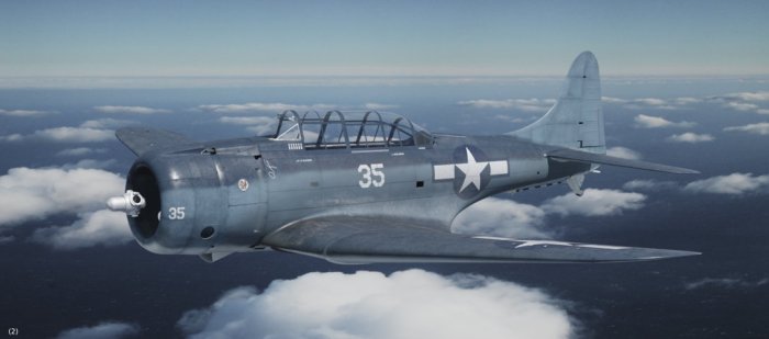
The next part I am going to recreate is the R-1820 engine (a simplified version, for the external pictures). However, for reasons beyond my control I have to take a break from this project. I will write next post in the spring (2018). So, for time being my SBD will look like this:
In this source *.blend file you can evaluate the SBD-5 model. Just for the convenience I am also placing here: the SBD-3 model in the ‘1942’ textures and their GIMP source, as well as the latest version of the Inkscape source file (this is the vector source the basic bump, ref, and transparency maps).

Great information as usual Witold.
I hope everything is ok with you.
LikeLike
Thanks, Dave! I am OK, just most of my “daily” work has to be done every winter!
LikeLike
Hey Witold,
Incredible work like usual!
When modelling, do you line-up your perspective reference images like in figure 82-9? If so, how do you go about doing it with reasonable accuracy?
Cheers,
Alex
LikeLike
Thank you, Alex!
Yes, I am using these photo during modeling like scale plans. (You can see another case in Figure 82-5). Of course, the most laborious task is to find a precise projection that matches given photo. (I described this process in the earlier posts. I have corrected it twice since the initial setup). Once I found it, I place a “first approximation” of the modeled part in this photo, then I am correcting it by shifting some vertices, usually along the axis of the local coordinate system of the modeled object. In case of such a moveable part as this tail wheel I had to take into account that every photo depicted it in different position. To minimize eventual errors I simultaneously work with several matched photos (I even wrote a special Blender “reference image palette” add-on, which allows me switch between these photos with a single click. I will show it in this blog, in a tutorial about the matching the model to the photos – I am going to write it in October).
Thanks to the high resolution of these Dauntless reference photos I estimate the maximum error of this method in case of large parts (whole wing, whole fuselage) to less than an inch. In case of he smaller parts (as the tail wheel) this error is proportionally smaller (a fraction of an inch).
LikeLike