In the SBD Dauntless the fillet along the fin and the fuselage was formed from the bent bottom edges of the fin panels. I am showing it in Figure 36‑1:

(To make some of these panel seams more visible on thee photos, I sketched along them thin lines). You can observe that each fin panel overlaps the next one, starting from the tip stamped as the part of one of the fuselage doors (see Figure 35‑8 in the previous post). The outer contours of these panes are not perfectly aligned: you can see small overlaps on the photos (Figure 36‑1). Surprisingly, such a detail makes the modeling more difficult. However, the most difficult part will be the seam between the fin and the horizontal tailplane fairings (see Figure 36‑1). It runs along the fuselage longeron, across the fillet between the stabilizers and fuselage.
Well, I started this fillet by extruding some faces from the bottom edges of the fin mesh (Figure 36‑2):
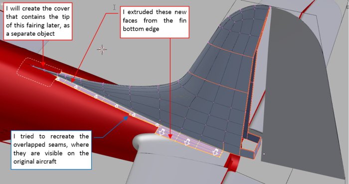
As you can see, I already recreated the sharp panel corners in these extruded faces. Then I lowered their outer edges and aligned them to their contours on the top view (Figure 36‑3):
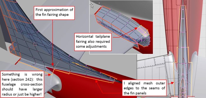
This is the first, rough approximation that fits these panels to the fuselage surface. In this process I discovered that I had to make some modifications to the upper part of the tailplane fairing (Figure 36‑3). However, I was not entirely satisfied with the result: comparing to the photos, something was wrong at station 242 (see Figure 36‑3). The outer seam of the fin fillet should be a little bit wider here!
After some additional deliberations I decided that the fuselage under the fin was somewhat higher (by about 0.5”) than on my reference drawings, and the upper arc of these bulkheads had larger radius. Thus I had to modify this part of the fuselage (Figure 36‑4):
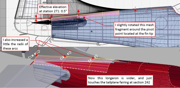
I rotated a little this mesh fragment, then scaled up the upper part of each of its three bulkheads.
I had no photo of the SBD fuselage without the fin, taken from the side. In fact, the shape of this fragment on my scale plans is in 80% my assumption! Such small anomalies as this one helps me to discover the real shape of this airplane.
Basing on the corrected fuselage, I was able to fit better the outer edges of this fin to the fuselage and the tailplane fairing (Figure 36‑5):
However, I was not satisfied with the forward part of the seam between these two fairings: despite all my efforts, it looked a little bit sharp!
Ultimately, I had to reshape a little bit the tailplane fairing and cut out the excess of its surface along this seam using a Boolean modifier (Figure 36‑6):
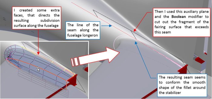
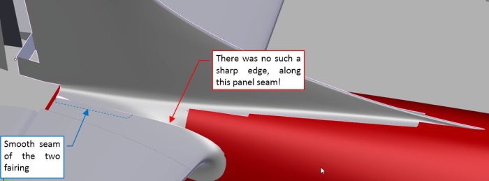
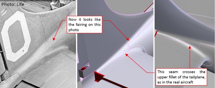
This method produced results that resemble the smooth shape that I can see on the photos (Figure 36‑7):
However, I do not like such a “Boolean – based” solution. It seems too complicated. In the next post I will try to eliminate such a “hard” seam between these two panels. I think that much better solution here will be a continuous, smooth surface. The seam can be recreated later, using textures.
Anyway, in this source *.blend file you can evaluate yourself the model from this post.

Awesome Job!!
LikeLike
Thank you very much!
However, as I wrote at the end of this post, I am not satisfied with this fairing. I will fix it next week!
LikeLike