On the first glance the SBD center wing section seems to be a simple rectangular (i.e. constant chord) wing, with modified leading edge (Figure 18‑1):

However, the landing gear openings visible on the photo can be difficult to recreate in a mesh smoothed by the subdivision surface modifier.
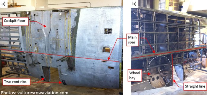
Additional photos from one of the SBD restorations made by Vulture Aviation in 2012-2013 reveal that the fuselage was mounted on the top of the wing (Figure 18‑2a):

A part of the upper wing surface was simultaneously the cockpit floor. Note the rectangular cutout in the middle of the leading edge. The SBD had a small window on the bottom of the fuselage, in the space between the two root ribs.
On the photo of the bottom of this wing (Figure 18‑2b) you can see that these root ribs had a modified airfoil shape: it bottom contour has a straight edge from the leading edge to the main spar.
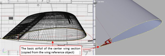
I started to form the center wing section by preparing the single curve of its external rib (Figure 18‑3). (I copied it from the root rib of the wing reference object, which I used during modeling of the outer wing panel):

I think that creation of these large landing gear bays (as in Figure 18‑1) will require a lot of modification in the wing mesh. Thus I decided to separate the mesh fragment that contains these openings (from the leading edge to the main spar) into a separate object. (It is always easier to modify topology of such a medium-size mesh part, than the whole wing). To ensure a smooth, invisible seam between this forward and the rear part of the wing, I had to accordingly prepare the control polygon of the initial airfoil. I added an additional point on each side of the vertices located above and below the spar line (Figure 18‑4):

What’s important, such three points have to be collinear. The resulting subdivision surface “touches” the middle point of such a fragment of the control polygon, and it is tangent in this point to these two adjacent control polygon segments. (This is just one of the mathematical properties of the Catmull-Clark subdivision surfaces, which are implemented in Blender).
However, these four new control points altered the shape of the airfoil curve. Now I have to fit this shape to the original NACA-2415 airfoil of the outer wing panel (Figure 18‑5):

Fortunately, the Catmull-Clark curves/surfaces have another property similar to the NURBS: so-called local change. Their formula ensures that influence of a single control point does not exceeds two subsequent segments of the control polygon (two segments in both directions — see Figure 18‑5, right). It is easier to focus on the modified mesh fragment, when you know this rule.
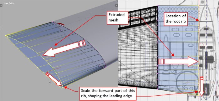
Once the initial rib shape fits the outer panel, I can extrude it forming the center wing section (Figure 18‑6):

To shape the leading edge I had to stretch a little bit the forward part of this mesh. As you can see (Figure 18‑6), I placed this new edge loop in the place of the wing root rib.
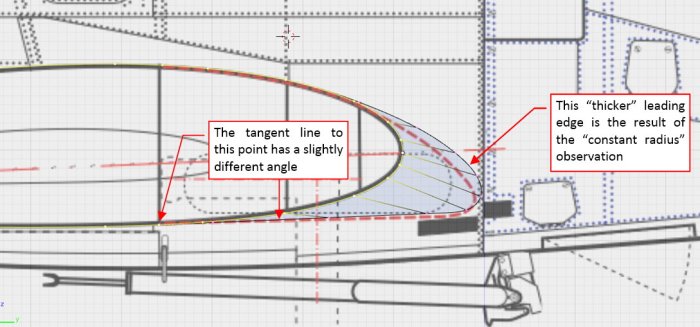
However, comparing the resulting object with the photos I discovered that the leading edge of the center wing section should have constant radius (at least approximately — see Figure 18‑7):

In this way I have found another error in my reference drawing: the wrong shape of the root airfoil (Figure 18‑8):

The tangent direction at the wing spar differs from the direction estimated on the drawing, thus the bottom, straight segment of the root airfoil has a slightly different slope. The leading edge is much thicker than I draw on these plans.
Adapting the well-known von Moltke’s sentence: “no plan survives contact with the enemy” to this situation, we can say that “no scale plans survive contact with their 3D model”.
I created a first approximation of the main wheel (it lacks the details) to check if it fits into the space between the leading edge and the main spar (Figure 18‑9):

When I was sure that the shape of the wing is OK, I separated the forward part of this mesh (by splitting it along the main spar). As you can see (Figure 18‑9, right) these two parts join in a seamless way. It was quite simple to prepare such an effect in the initial curve by adding additional control points (see Figure 18‑4). It would be much more difficult to introduce similar modifications into the extruded mesh.
If you want to learn more about properties of the Catmull-Clark subdivision surfaces, as well as the details of the modeling workflow, see Vol. II of the “Virtual Airplane” guide.
In this source *.blend file you can check all details of the wing presented in this post.
In the next post I will create the opening for the landing gear.
WOW! What is the Airfoil profile of this airplane and how much twist are you applying to the tip?
LikeLike
The SBD wing uses the NACA 24x series airfoils. In the wing joint it is NACA-2415. The root ribs at the fuselage use the same NACA-2415 airfoil, but – as you saw in this post – it has the modified leading edge (to accommodate the wheels) . The airfoil at the base of the rounded wing tip is NACA-2409.
I suppose that writing about the twist of its tips you mean the wing wash-out. There is none – the whole SBD wing has fixed incidence angle (2.5deg). I am not sure, but it could be the Spitfire which utilized the first wing wash-out in a serial airplane. For example: the Bf-109 and P-36 had none – because they were designed for the mass-production, while it complicates the technology of wing manufacturing. The approach of the Spitfire designer was completely different – he decided to sacrifice the technology (i.e. cost and time) for better performance.
The aerodynamic concept of the SBD wing originates in the Northrop Alpha airplane (1930). In that time the cantilever monoplane was a novelty, and – as I suppose – there was no special research on its stall characteristics. It served badly the direct SBD predecessor – the Nortrop BT-1. The BT was haunted by poor stall characteristics, which make it difficult to use on the flattops. (No surprise, taking into account the fixed incidence angle of its wing). To save this project, its designers resolved this problem by applying in the SBD fixed slats at the wing tips. It was less elegant solution than wing washout (it generates more drag), but it worked and did not require significant changes in the wing geometry (i.e. the tooling => the costs). A few years later the designers started to use not only the simple “twisting” wash-out, but also aerodynamic wash-out. I have read that the wing of B-25 “Mitchell” had both: the twisted wing tips and different families of the airfoils at the tip and the wing root.
LikeLike
Thorough as always Witold.
I like your observation regarding the difficulty of modifying objects after applying a subdivision surface modifier. After a few frustrating exercises I went back to creating high poly wings- I found it gave me more control. If needed I applied the sub d at the end.
LikeLike
Thank you!
However, I just wanted to show how to keep the relatively simply mesh, simultaneously using subdivision surfaces and other modifiers to obtain the desired results… I have learned that before I start a new mesh fragment I have to:
1. identify the openings I want to create (usually I have to put a sharp [Crease = 1] edges around them);
2. identify the other shar edges;
3. determine the distribution of the control points on the initial cross section, to create the edges from 1) and 2). Some of them still have to be smooth – and you can obtain this effect by two adjacent colinear segements of the control polygon (as I show in this post);
Well, there is nothing wrong in using dense meshes. I try to keep them simpler because:
– I can always find in the later stages of work that the shape of some elements finished earlier is wrong. It will be easier to modify them when they have simpler mesh;
– It will be easier to unwrap them in the UV space;
On the other hand, in my programmer’s experience I always feel that one should be very careful with deciding that something is impossible to obtain – becasue you are cutting out in this way a whole “tree of possible solutions”. Maybe I can help you with an especially difficult case? Just send me it in an e-mail 🙂
LikeLike