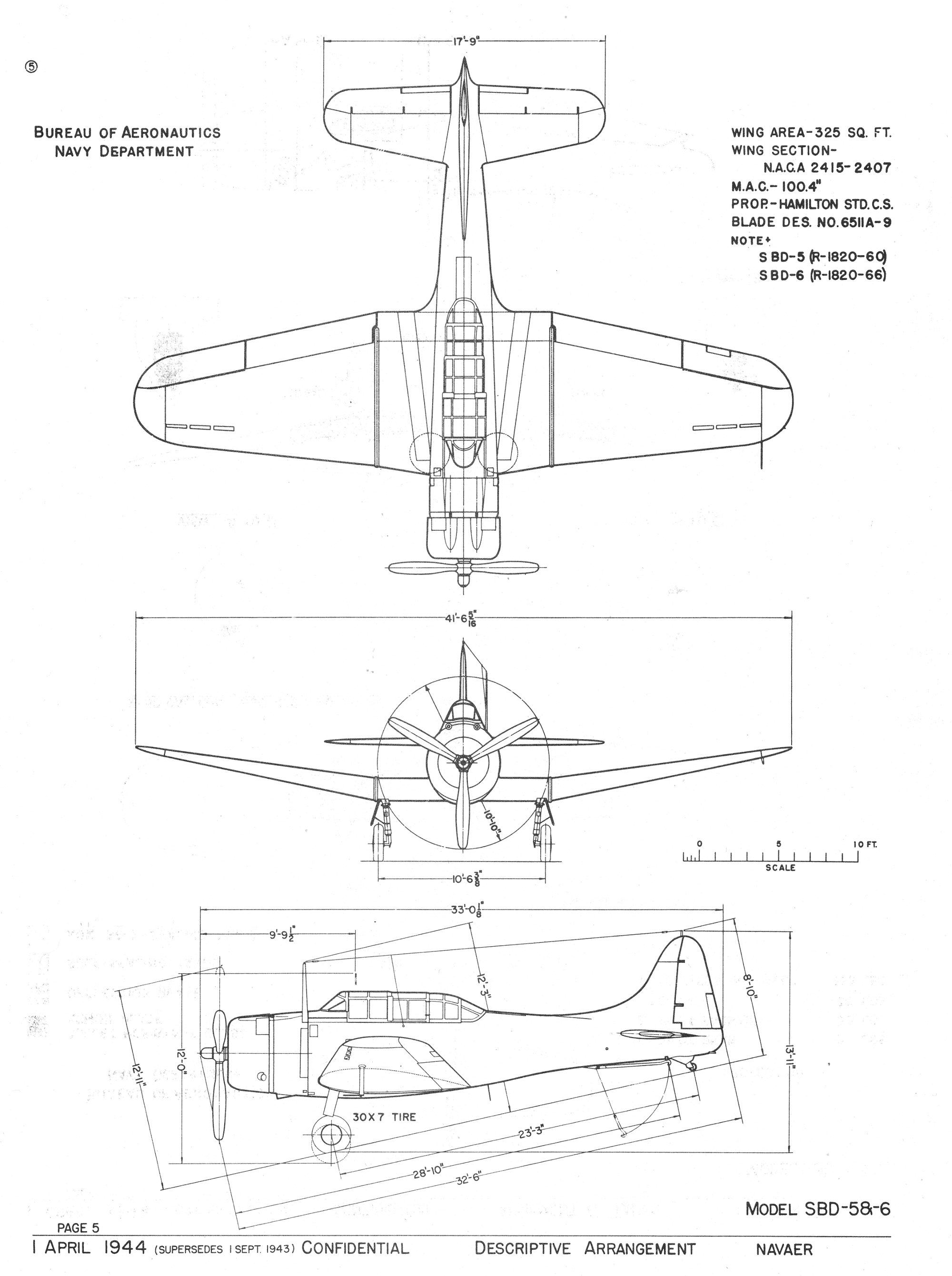
In my previous post you can find the updated scale plans of the SBD-5 Dauntless, consisting the side and top views. The ultimate shape of depicted airplane resulted from matching my initial drawings against the Douglas general arrangement diagram. I couldn’t do it before, because this diagram comes from the Dauntless maintenance manual, which I received in previous week.
In this post I will show you how I do such a matching using the diagram shown below:

When you use such a drawing, you can follow the general rules of the technical drawings. In particular:
- The ultimate contour of the depicted object is on the outer side of the drawing lines;
- When the shape on the drawing differs from the result of its explicit dimensions, the result of these dimensions prevails;
So, starting from the thrust line (i.e. the propeller axis) and from the firewall (the base of all dimensions), we can use the dimensions from this diagram to determine the wing chord position (points A and B in Figure 7‑2):


Figure 7-2 Chord dimensions of the key wing rib
We can read from the side view dimensions that A (the rib tip) is located 20.38” from the thrust line and 9” from the firewall. The end of this rib is located 2.5⁰ lower, and the chord length of this rib is 115.12” (this dimension you can read from the top view). This determines location of point B.
I used the scale of my drawing (3.02 px/in) to convert the dimensions listed above into drawing units. Then I used guide lines to find these points of the wing chord on my plans (Figure 7‑3):

Fortunately points A, B on my plans occurred very close to wing leading and trailing edges.
You can use dimensions from the general arrangement drawings to sketch the basic trapeze around the wing (in the top view) as well as around the fin, rudder, and horizontal tailplane. These trapezes allow you to determine the basic shape and proportions of the airplane. I will show this method on the example of the fin and the rudder. Figure 7-4 shows their dimensions on the original drawing:

Using these dimensions you can draw the basic trapezoid around the rudder and fin. You can also locate the chord of the horizontal tailplane as we did for the wing.
When I mapped these elements onto my plans, they revealed a serious flaw in my drawings (Figure 7‑5):

The whole tailplane seems to be shifted downward, and the rudder hinge is moved left! However, if the wing chord fits to the dimensions, then most probably this is the result of a random rotation. I have quickly verified this hypothesis using the reference photo (Figure 7‑6):

When I set the pivot point of this transformation above the wing (Figure 7‑7), it was enough to rotate this photo by 0.27⁰ to fit the rudder and fin into given contour:

It seems that I made mistake at the very beginning, trying to set this photo horizontally (in this post). I estimated it using cockpit edge (as in Figure 7‑6), because the better candidate for such a reference — the seam running on the side view along the reference line — is not visible on this picture. It seems that this fragment was too short for precise estimation of the horizontal direction. What’s more, I did not know at the beginning that in the top view this edge is not parallel to the fuselage centerline. Because the depicted airplane is slightly inclined toward the photo, I had to estimate location of this edge as the line lying between two cockpit edges visible on this picture. The BuAer drawing (copied from the Douglas general Arrangement Diagram) would help, if its draftsman did not made additional errors around the tail and empennage (see Figure 2‑4 from this post).
Of course, the drawings that I published in the previous post did not contain any of the flaws that I have found here. I fixed all of them before. I just wanted to show you in this post what kind of errors you can do using a photo reference.
Conclusion: always try to find a general arrangement diagram of the airplane and use its explicit dimensions to verify your drawings. They often allow you to fix severe flaws in the geometry of the depicted aircraft!

This is really good stuff, Witold. As you’re indicating, and as I’ve learned independently myself, the temptation to start modeling with the first 3-view you find must be resisted. It actually pays to get things right in these early stages. For one thing, It makes the modeling and texturing later much easier when all the underlying geometry description is self-consistent. It begs the (rhetorical) question, though, at what point do you bite the bullet, declare you’ve enough documentation, you’re drawings are good enough, and actually start modeling? You’re always sure to find more and better information the longer you look. I guess you just have to be ready to make late changes as you’ve demonstrated on your P-40.
Thanks again for all the great information!
LikeLike
I think that I will finish these drawings within three weeks. (Currently I am working on the bottom view, then I will draw the front view and the fuselage cross sections). Of course, it may happen that I will have to update them in the future. However, the general shape and locations of the main elements were verified against the “hard” dimensions, and all of the ribs and bulkheads are placed precisely at locations specified by the stations diagram. I also noticed that now I do not have to change lines on these drawings too often. So it seems that now these drawings are “stable enough” to be used for the 3D model.
At this moment I will not draw the cockpit interior or landing gear details. I will do them later, when I start detailing.
LikeLike