I already finished the bump map (in the second-last post), so it’s time to introduce another texture: the reflection (ref) map. It alters the basic reflectivity (gloss) assigned to the material. In addition, it also alters the material “roughness”. (In the typical CG materials the roughness and reflectivity are coupled in an inverse proportion). These two parameters are important, when you have to paint an oil streak or a soot streak. Both are black – the difference between them lies in their reflectivity.
The effects of the ref map are most visible inside these areas of the model that actually reflect the light:

Figure 73‑1 shows two renders of the same model: the upper one was created without any reflectivity map, the lower one uses a basic ref map. (I created this texture around the technical details of the aircraft skin).
Compare the rivets seams in these two pictures, especially in areas (1) and (3). As you can see, ref map “emphasizes” these elements. In the lower picture the rivets and panel seams look more weathered than in the upper picture. The same applies to the bolts (2). In general, I use the reflectivity map to recreate the weathering and dirt that accumulates on the aircraft. Of course, the dirt pattern of this texture has to be tightly coupled with the corresponding pattern on the color map. (I will describe it in the next post).
I composed the basic reflectivity map in Inkscape, using three overlapped pictures. I briefly describe this composition below, on a representative fragment of the texture: the wing tip. (This fragment is small enough to make visible the minor details of this image. You can also examine the source Inkscape file for the further details). The first component of this texture is a blurred image of the basic rivet seams (Figure 73‑2):

It contains clones of three source layers: Rivets:Dome (turned black), Rivets:Flush, and Shadows. To alter the color of the Rivets:Dome layer clone to black, I used an auxiliary SVG filter that contains just a single ColorMatrix component. Similarly, to blur the contents of this Ref-Details:Blur layer, I used another SVG filter, that contains a GaussianBlur component.
The other component of this texture emulates the small, random dirt and scratches that accumulate around all seams. I named it Grunge (Figure 73‑3):
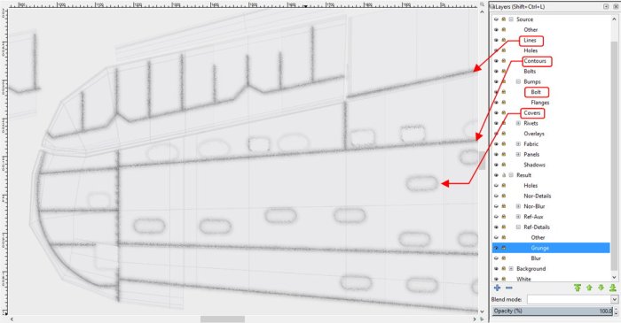
I composed this picture from clones of the Lines, Contours, Bumps:Bolt and Covers layers. Their contents is “dispersed” here using a special SVG filter. (For details of this solution, see “Virtual Airplane” guide, chapter about Inkscape, section about the dirt effect). I used here a new layer Contours, which I have not mentioned in previous posts. It contains just outer outlines of some selected elements (for example – cowling panels), drawn using thicker black line. (Such a line adds additional dirt along their edges).
I placed the dirt image (Ref-Details:Grunge layer) over the blurred panel lines (Ref-Details:Blur layer), and placed on top of them another layer named Ref-Details:Other. It contains clones of the Rivets, Fabric:Stripes, Covers, and Bolts layers. The idea is that this layer “clears the dirt” off the protruding skin elements (that’s why the clone of originally black Rivets:Flush layer is white here). Figure 73‑4 shows the final composition of the Ref-Details texture:

The basic elements of this image – clones of the source layers – will update automatically, when I change one of the original layers. This feature is important for me, because I often have to introduce small corrections to the model, even during the last, detailing phase of the project. (You never know, when you find a new picture or drawing, which reveals that a particular detail in your aircraft had a different shape). Some of these corrections require corresponding changes in the textures. The automatic update of the three basic textures (two bump maps, and this reflectivity map) is a great help in such a case.
I exported contents of the Ref-Details layer into a file named ref_details.png, and connected it to the material scheme (Figure 73‑5):

Because this Inkscape image re-uses the same components as in the bump maps, the reflectivity texture uses the same UV layout (UVTech). I connected this texture to two sockets: Ref Image and Dirt Image. The max. (i.e. basic) reflectivity is controlled by the Reflectivity parameter, while the contents of the ref texture decreases this value locally, in appropriate areas. The intensity of this effect is controlled by the Range parameter in the auxiliary Range To Max control node. To control the dirt effect I use the Dirt Intensity parameter (there is no need for another Range To Max control node on this line, because the basic Dirt Intensity = 0). (For explanation of the inner details of the X.Textured Skin group, see “Virtual Airplane” guide, chapter “Texturing the Model”, section “Summary”).
The dirt is hardly visible on the metal surface kept in the “natural finish”. (You can see the effect of this reflectivity map on such a surface in the first figure in this post). Om this example I switched the material to the non-specular Navy Blue-Gray color (see Figure 73‑5). The U.S. Navy and Marines used this color to paint the upper and side surfaces of their aircraft in 1941, 1942 and 1943. This is just the first approximation – a solid color for all surfaces. (I will create the proper color texture in the next post).
Figure 73‑6 shows the result of applying the reflectivity/dirt map (connected as in Figure 73‑5) to a low-specular surface:

Still, the aircraft depicted in the figure above seems “too clean”.
To further enhance this dirt pattern, I combined the original image with a random “noise” pattern (Figure 73‑7a). This random pattern is composed from two different Noise Texture nodes of different size. One of them creates big darker and lighter “clouds”. I set the intensity of the General Noise texture (in the accompanying Range To Max node) so that its darker “clouds” have similar shade to the elements of the of the ref_details.png image. It makes the resulting dirt/ref pattern less regular (see Figure 73‑7b):
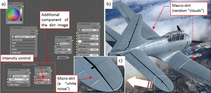
The other component of the General Noise pattern creates a “white noise” of small darker and lighter spots (see Figure 73‑7c). It resembles the real micro-dirt, dispersed evenly on the whole aircraft surface.
On all SBDs you can see anti-slip stripes running along both sides of their fuselages. Its surface was painted in the factory with a special “rough” paint. It seems to have much lower light reflection than the rest of the aircraft surface. I will recreate this reduced reflectivity of this strip on the ref texture, while I will paint it in black later, on the color texture.
It seems that the anti-slip strip is longer on the restored aircraft than on the photos of the original SBDs. To determine its true (i.e. original) size and location, I used the archival photos, as well as the contemporary photos of the few SBD wrecks (taken before their reconstruction). Below you can see two of these photos (Figure 73‑8):

Figure 73‑8a) shows the original state of the SBD-5 restored by the Pacific Aviation Museum, while Figure 73‑8b) shows the SBD-3s on the deck of USS “Enterprise”, on April 4th, 1942. It is a good photo, because it shows multiple aircraft belonging to the same squadron. You can see on these bombers that the anti-slip stripes extend from the trailing edge to the main spar of the wing. Precisely the same span you can see in the original SBD-5 from Figure 73‑8a). However, on some airplanes that I saw on the photos the anti-slip strip is extended over the main spar, into the area that I marked in Figure 73‑8a) with white outline. I suppose that this forward part of the strip could be painted in black by the local crews. It seems that they used various paints for this purpose, sometimes even the glossy ones.
At this moment I recreated this strip in its standard shape: from the trailing edge to the main spar. For this (and other, similar) purpose I made an auxiliary reflectivity map, and named it ref_aux.png (Figure 73‑9a):

You can see that I drew the anti-slip stripe in black there – this means that this area will have the minimal reflectivity (and maximum roughness). Thinking about the eventual glossy fragment at the end of this strip, as well as the oil streaks that I will paint in the next post, I set its background color to neutral gray (50% black). All the glossy elements will be lighter than this color. In addition to the strip, I decided to decrease the reflectivity of the fabric-covered control surfaces. (The fabric surface is rougher the metal surface, even when you paint them using the same paint). Because this difference in material reflectivity is not as intensive as on the anti-slip strip, I filled the aileron, elevator and rudder outlines with a dark gray instead of black.
Figure 73‑9b) shows that I mixed these auxiliary and basic ref maps using a Multiple node. This means, that now the background color of the resulting image is close to the neutral gray (it was 92% white, before). To compensate this difference, I had to increase the basic Reflectivity (the parameter in the X.Textured Skin group) to the maximum.
Figure 73‑10 shows the result of this additional ref map:

In Figure 73‑10a) you can clearly see the anti-slip strip as a dark area on the center wing. Similarly, the fabric-covered aileron is also somewhat darker than the rest of the wing tip surface. However, this effect depends on the incoming light angle. When you look at this model from the opposite direction (as in Figure 73‑10b), you will notice that these areas are lighter! In the real world, you can find the same effect on the photos of the aircraft painted with non-specular paints.
Figure 73‑10c) shows the final effect of the reflectivity maps, created in this post. In fact, this is just a beginning: this texture represents an “overall dirt”, evenly dispersed on the whole aircraft. Now I have to add the soot and oil streaks that appear on every real piston-engine airplane. The radial R-1820 engine (and especially its exhaust stacks) provided plenty of interesting patterns on the SBDs fuselages and center wings. However, I want to paint this dirt simultaneously on the reflectivity map and the color map. Thus in the next post I will prepare the basic color (diffuse) texture, then we will return to the “dirt painting”.
In this source *.blend file you can evaluate yourself the current version of the model, and here is the source Inkscape file of its textures.

2 thoughts on “Creating Textures: Reflection Map (1)”